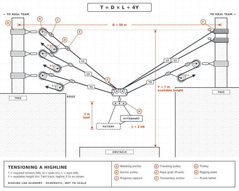
The full span is visible with the formula T=DL/4Y displayed at the top. The span is annotated at 50 metres anchor to anchor. A vertical orange arrow drops from the carriage level downward, annotated at 7 metres total. A dashed bracket alongside the load package shows 2 metres — the vertical depth occupied by the rescuer and patient below the carriage. A 2 kN load label identifies the combined weight. At the bottom of the gorge, trees mark the obstacle the system must clear.
Every highline in this series carries the same two people — a rescuer and a patient — across a gap. What changes is the span, the available height, and the terrain below. What never changes is this: before a single line goes into tension, someone on the team must calculate exactly how much tension the system requires. Not approximately. Not by feel. Exactly. This image shows how that calculation works and what it is actually measuring.
The formula at the top of the image is T = DL / 4Y.
T is the required tension in kilonewtons — the number that must be in each trackline before the load goes on. D is the span distance in metres — 50 metres in this example, measured anchor to anchor. L is the combined load in kilonewtons — 2 kN here, representing the rescuer and patient together. Y is the available height in metres — and this is where the majority of errors are made.
What it is. The formula calculates the minimum trackline tension required to keep the two-person load at the intended height above the terrain below. In this image that terrain is the trees at the bottom of the gorge. The load must clear them. The orange vertical arrow shows 7 metres of total available height between the carriage and the tops of those trees. That is Y — but read the image carefully. There is a second annotation: 2 metres, marked with a dashed bracket alongside the load package itself. That 2 metres is the vertical depth of the rescuer and patient below the carriage. It is not open air. It is occupied by two people. Which means the usable clearance between the bottom of the patient and the tops of the trees is not 7 metres. It is 5 metres. Y = 5, not 7.
Applying the formula with the correct Y value: T = (50 × 2) / (4 × 5) = 100 / 20 = 5 kN per trackline.
Use the incorrect Y value of 7 and the calculation gives 3.57 kN — a result that feels acceptable but places the patient 2 metres lower in the span than calculated, directly into the tree canopy below.
Why it is built this way. The formula exists because the relationship between sag, tension, and anchor force is not intuitive and is not linear. A team that tensions by feel will almost always under-tension on long spans — the lines look tight long before they reach the required value — and will almost always misjudge clearance because they are estimating from the anchor rather than calculating from the load. The formula removes both errors simultaneously. It tells the team what tension to build to and what clearance they will have when they get there.
The physics. The catenary geometry of a loaded span means that the tension in the tracklines must do two things at once: resist the downward pull of the 2 kN load at mid-span, and resist the inward pull toward the centre of the span that the sag geometry creates. The shallower the sag — the tighter the lines — the greater the inward force component at the anchors. This is why anchor forces in a highline are always a multiple of the suspended load, not equal to it. On a 50 metre span tensioned to 5 kN per trackline with a 2 kN load, each anchor is not absorbing 1 kN. It is absorbing the full vector sum of the trackline tension pulling inward along the span axis — a force that is significantly greater than the weight of the people being carried.
Increase tension to reduce sag and that anchor force climbs. The relationship accelerates — halving the sag more than doubles the anchor force. This is the non-linearity that makes the formula essential and makes under-built anchors catastrophic on tight spans. A team that tensions beyond the calculated value because the span looks saggy has driven their anchor forces into territory the rigging was never designed to handle.
When it works. The calculation works when Y is measured correctly — from the carriage to the obstacle below, minus the depth of the load package. It works when the load cell on each trackline is used to verify that the calculated tension has actually been achieved. It works when the team stops tensioning when the load cell says stop, not when the lines feel right.
When it fails. It fails when Y is taken as the gross available height without subtracting the load package depth — as shown in this image, that error alone shifts the result by 1.43 kN per trackline and puts the patient into the terrain. It fails when tensioning is done without a load cell and the team stops at feel rather than at a verified number. It fails when the span distance or load is estimated rather than measured — because every variable in the formula compounds. A 10% error in D, a 10% error in L, and a 10% error in Y do not produce a 10% error in T. They multiply.
The two-person load effect. The 2 kN load in this formula is not an abstract number. It is two people — a rescuer in full kit and a patient whose weight, position, and movement cannot be precisely controlled. That load is dynamic. A patient who shifts during the crossing changes the effective load at mid-span moment to moment. The formula calculates for a static load. The system must be built with enough margin above the calculated tension that the dynamic reality of two moving people does not push it beyond its limits. The load cell target is the minimum. The system’s working margin above that minimum is what keeps two people safe when the load stops being perfectly static — which it always does.