Failure Begins When the Load Path Stops Behaving as Intended
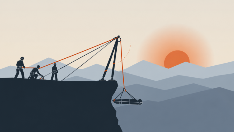
Failure in an elevated anchor system does not begin only when a leg bends, a connector breaks, or a frame collapses. Long before structural separation occurs, the system can begin departing from the geometry and load path for which it was designed.
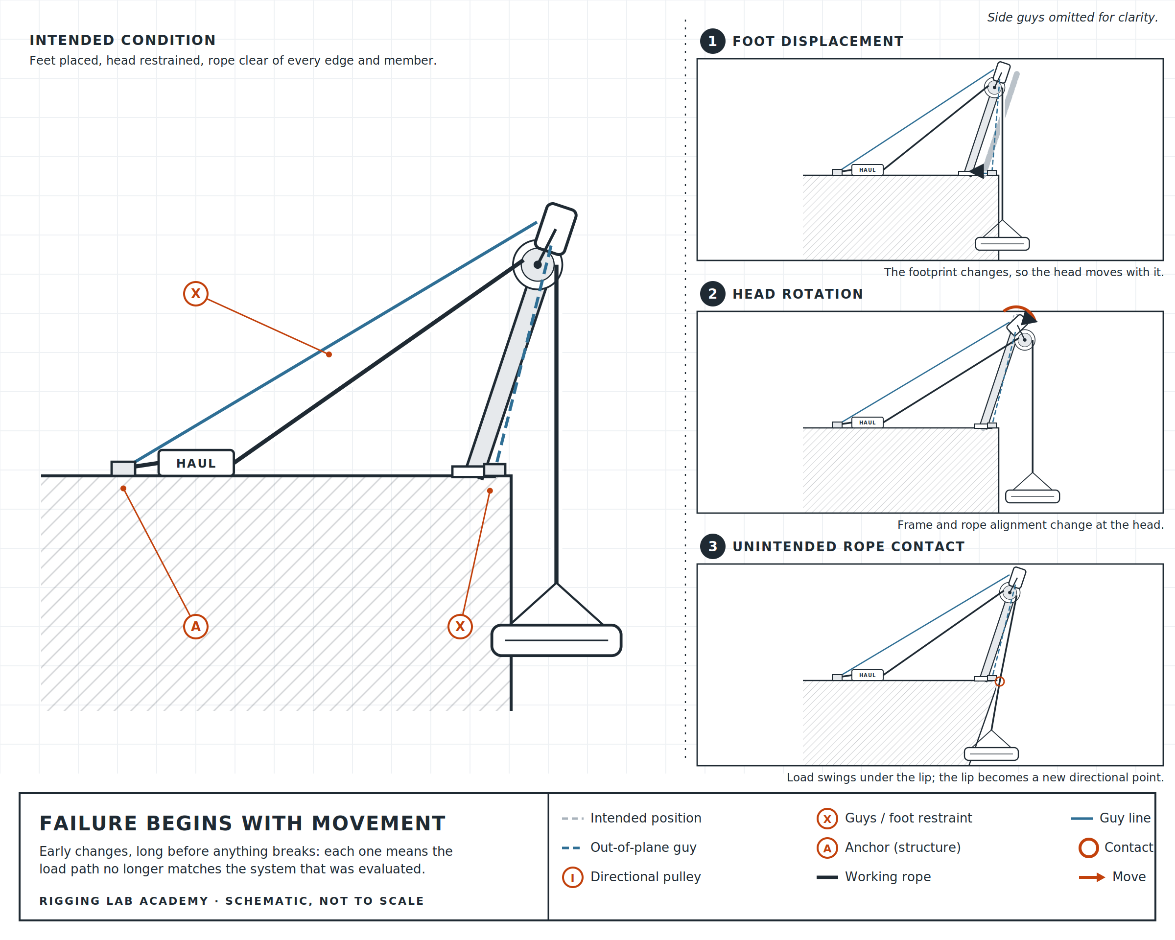
A foot can start to move. A head can rotate. A guy can lose tension. A rope can begin contacting a frame member and create an unintended directional point. A structural attachment can shift. A changing rope angle can move the resultant into a condition the restraint system was not intended to manage. None of those events is necessarily catastrophic by itself, but each indicates that the operating system is becoming different from the system that was evaluated, preloaded, and placed into service.
For that reason, failure prevention begins with a broader definition of system integrity. The objective is not simply to keep every component below its breaking strength. The objective is to maintain the intended relationship among the load, rope path, elevated point, compression structure, restraints, anchors, and supporting environment throughout the operation.
Once one of those relationships changes unexpectedly, the technician has to determine whether the system remains controlled or whether movement should stop while the load path is reassessed.
Loss of Foot Security
The feet establish the physical boundary through which many portable elevated anchors transfer compression into the supporting surface. If a foot moves, the geometry above it changes with it.
A tripod foot that spreads outward changes the base triangle and alters the relationship between the head and the supporting contacts. An A-frame foot that slips can rotate the entire frame plane. A monopod foot that shifts changes the axis of its single compression member and places greater demand on the surrounding guys. On hard surfaces, sliding may be the primary concern. On soft or irregular terrain, settlement, rotation, or loss of bearing support may be more important.
The safeguard begins by identifying the expected movement tendency before the load is introduced. Hobbles, foot restraints, surface selection, pads, lashings, or other approved methods are then selected to oppose that specific movement rather than being added generically after the frame is assembled.
Preloading should confirm that the feet remain where they were placed. Operational monitoring then confirms that they continue to remain there as the load moves and the resultant changes.
Visible movement at a foot is not something to normalize simply because the frame remains standing. The foot is part of the structural geometry. If its position changes, the geometry has changed and the effect on the entire system has to be understood before movement continues.
Head Movement and Frame Rotation
The head is the point where the working ropes, directional hardware, compression members, and restraints come together. Movement at the head therefore changes several relationships simultaneously.
A head that pitches forward or backward changes the angle of the legs, the effective position of the elevated point, the guy geometry, and the rope path. Rotation around the vertical axis can introduce torsion into the legs or force the rope against hardware that was not intended to carry side load. Lateral movement can pull the frame out of its original plane and transfer load into restraints that were initially carrying little force.
Different configurations naturally have different movement tendencies. A freestanding tripod may remain stable while the load stays within its established footprint but become increasingly susceptible to toppling as the load moves toward the perimeter. An A-frame requires more deliberate control of head movement because it does not have the same three-dimensional footprint. A gin pole depends heavily on its guy system because the single compression leg cannot independently resist movement in every direction.
The safeguard is to identify where the head will tend to move under both the planned operation and foreseeable disturbances, then provide restraint that directly opposes that movement. Guying should have a mechanical purpose. Each guy exists because there is a specific movement or force direction that it is intended to control.
Resultant Movement and Loss of Compression Alignment
The resultant is the combined effect of the forces entering the elevated point. When the rope geometry changes, the resultant can change in both direction and magnitude.
A structure that is intended to carry load primarily through compression performs best when that resultant remains aligned with the geometry designed to receive it. If the resultant migrates significantly away from that path, the system begins demanding more from guys, hobbles, connections, and the bending strength of the frame.
For a freestanding tripod, movement of the resultant toward the edge of the base reduces the margin against toppling. For an A-frame, an out-of-plane resultant can introduce torsion and lateral instability. For a monopod, even relatively small directional changes matter because there is only one compression member beneath the head.
Some advanced configurations deliberately operate with resultants that are not contained by a simple freestanding footprint. In those systems, external restraints are part of the structural design and must carry the forces required to maintain equilibrium. The safeguard is therefore not an oversimplified rule that every resultant must always remain geometrically inside every base. The requirement is that the resultant remains within the controlled structural condition established for that configuration.
This is why identifying the applied force, predicting movement tendencies, securing the feet, securing the head, and testing the loaded system form one continuous process.
Guy and Restraint Failure
A guy system can fail structurally, but it can also fail functionally long before the cordage or hardware breaks.
A guy that is poorly positioned may be strong yet ineffective because it does not oppose the movement of the head. A shallow guy angle can create unnecessarily high tension. A guy attached in a way that introduces torsion can stabilize movement in one direction while creating another problem elsewhere. A line that becomes slack during a transition may no longer provide the restraint assumed during setup.
The same logic applies to hobbles and foot restraints. A strong hobble that is too loose may permit enough initial movement for the structure to change geometry before the restraint becomes engaged. A restraint connected to the wrong point may introduce leverage rather than directly controlling the foot.
Safeguarding the structure therefore requires more than strong materials. The restraint has to be positioned, tensioned, and connected so its force actually opposes the expected movement.
Guy and hobble anchors are equally important. The restraint system can only be as effective as the anchors receiving its forces. A guy that becomes highly loaded during an offset or edge transition may impose a substantially different demand on its anchor than existed during initial setup.
The restraint system should be considered part of the primary structural system whenever the elevated anchor depends upon it for stability.
Supporting Surface and Anchor Failure
Portable frames transfer load into the environment through their feet and restraints. Structural high points transfer load through the selected attachment into the surrounding building, tower, natural feature, or supporting system. In both cases, failure can occur outside the rescue equipment itself.
A foot may punch through an unsuitable surface. Soil may settle. A rock feature may move. A structural member may remain intact while its connection to the larger structure is inadequate for the direction of loading. A guy anchor may pull, rotate, or deform even though the guy line remains undamaged.
This is why the strongest visible rescue component does not define system capacity.
The safeguard is to continue the load-path analysis beyond the frame. If compression enters a floor, the floor becomes part of the system. If a guy loads a beam, the beam and its connections become part of the system. If a tower member provides the high point, the surrounding structure carrying that force becomes part of the system.
Unknown structural capacity is not corrected by adding stronger rescue hardware between the rope and the structure. The uncertainty remains in the structural element.
Transverse Loading and Leg Instability
Frame legs are most efficient when the force travels predominantly along their length. When another object contacts a leg mid-span, the frame is twisted out of plane, or the load path places substantial force across the leg instead of through it, the structural condition changes from primarily axial loading toward bending.
That distinction matters because a long tubular member that carries substantial compression along its axis may have considerably less tolerance for the same magnitude of force applied transversely.
This is also one reason taller and more extended configurations require greater discipline. Longer members provide more opportunity for bending and deflection, and small misalignments at the head can create greater displacement farther down the leg.
The safeguard is not simply to use stronger legs. The better approach is to maintain the geometry for which the structure was designed: keep compression members clear of unintended contact, avoid leaning objects against them, prevent rope systems from loading them at mid-span, and position the head so the anticipated resultant aligns with the intended structural path.
If the frame requires substantial bending strength to remain stable, the technician should question whether the geometry itself needs to be changed.
Connection and Hardware Failure
Modular high directionals depend upon multiple mechanical connections. Pins join legs, feet, and head assemblies. Connectors attach ropes and restraint systems. Pulleys establish the directional rope path. Each of those components has to perform both structurally and mechanically.
A pin that is not fully seated can allow separation. A connector that becomes cross-loaded can operate outside its intended orientation. A pulley that is incorrectly installed can place rope or hardware against an unintended surface. A damaged or misaligned joint can introduce movement that was not present in the original assembly.
The inspection discipline developed in Lesson 6.2 is the first safeguard. Correct assembly is the second. Preloading is the third.
A properly assembled system should behave as a unified structure when the test load is introduced. Connections should remain seated, the frame should not develop unexpected play, and moving hardware should continue operating through the intended rope path.
Once the operation begins, those same connection points remain part of the monitoring process. Hardware that was correct when unloaded can still become poorly oriented if the rope path changes substantially.
Rope-Path Failure and Unintended Directionals
One of the less obvious failure conditions occurs when the rope stops following the path that was originally analyzed.
A rope can begin contacting an edge, rail, frame leg, head plate, connector, or structural member. Once meaningful tension is transmitted through that contact, the system has effectively gained another directional point.
That changes the load path.
The technician may notice this as increased friction, a change in hauling effort, altered lowering response, unexpected movement at the frame, or visible displacement of the rope. The rescue load may not have changed at all, but the forces arriving at the elevated structure may now be different.
The safeguard begins with sufficient clearance and deliberate rope routing. The working ropes should enter and leave the directional hardware cleanly through the entire anticipated movement of the load. The team should also consider how that relationship will change during an edge transition or horizontal movement rather than evaluating the rope path in one static position.
If unexpected rope contact develops during the operation, simply pulling harder is not a solution. The new contact must be understood because it may have changed both friction and structural loading.
Overload and Capacity Exceedance
Structural overload occurs when the force imposed on a component or configuration exceeds the condition for which it is rated or otherwise established as acceptable.
The difficulty is that the rescue package itself does not always reveal that force. Directional pulleys combine rope tensions. Shallow horizontal systems can produce large anchor forces. Guy tension can increase dramatically as guy angles become shallow. Dynamic movement can produce forces beyond the static condition used during setup.
Lesson 6.1 established the distinction between payload and applied force. In failure prevention, that distinction becomes operational. The technician must compare the largest force reasonably expected during the operation with the allowable condition of the components and structure carrying that force.
The safeguard is therefore partly numerical and partly geometric. WLL and structural ratings establish limits, while rope angle, pulley configuration, guy angle, frame extension, and direction of loading determine how closely the operation approaches those limits.
Staying below a published number while using the structure outside its intended geometry is not a valid capacity assessment.
Dynamic and Unplanned Movement
Not every force change can be eliminated before the operation begins.
A litter can swing. A rope can suddenly clear an edge and lose friction. A load can rotate. A hauling team can change direction. Wind can influence a suspended package. A surface can settle under load. An operator can stop or start a movement more abruptly than intended.
The purpose of system design is not to pretend these possibilities do not exist. It is to consider the foreseeable ones when establishing the structure.
Movement tendencies should therefore be considered in at least three conditions: before the system is loaded, during the planned movement of the load, and during foreseeable deviations from that plan.
A tripod positioned safely for a perfectly centered vertical load may need additional restraint if the package could swing outside the footprint. An A-frame that remains stable during a slow raise may require greater control if the litter will transition over an edge. A monopod that depends entirely on three or four guys has to remain restrained through the range of directions the load may reasonably take.
Safeguards provide enough structural control that a small operational disturbance does not immediately become uncontrolled frame movement.
Test Loading as a Safeguard
The controlled test load connects the predicted system with the physical system.
Before personnel are committed to a hazardous position, the frame should be loaded in a safe, controlled manner that represents the anticipated operational condition as closely as practical. The purpose is not simply to prove that the equipment can hold weight. The purpose is to see whether the complete system behaves as predicted.
The technician observes the feet for spreading, sliding, settlement, or rotation. The head is watched for pitching, twisting, or lateral displacement. Guys and hobbles are observed as they assume load. Structural attachments and supporting surfaces are checked for movement. The rope path is confirmed under tension rather than only while slack.
If the system moves unexpectedly under the test load, the correct conclusion is not that the test has “settled everything into place.” The movement has provided information. The cause must be understood, the system adjusted where appropriate, and the test repeated until the behavior matches the intended structural condition.
Test loading is valuable precisely because it gives the system an opportunity to reveal errors before the operational load is committed.
Safeguards Work as a Sequence
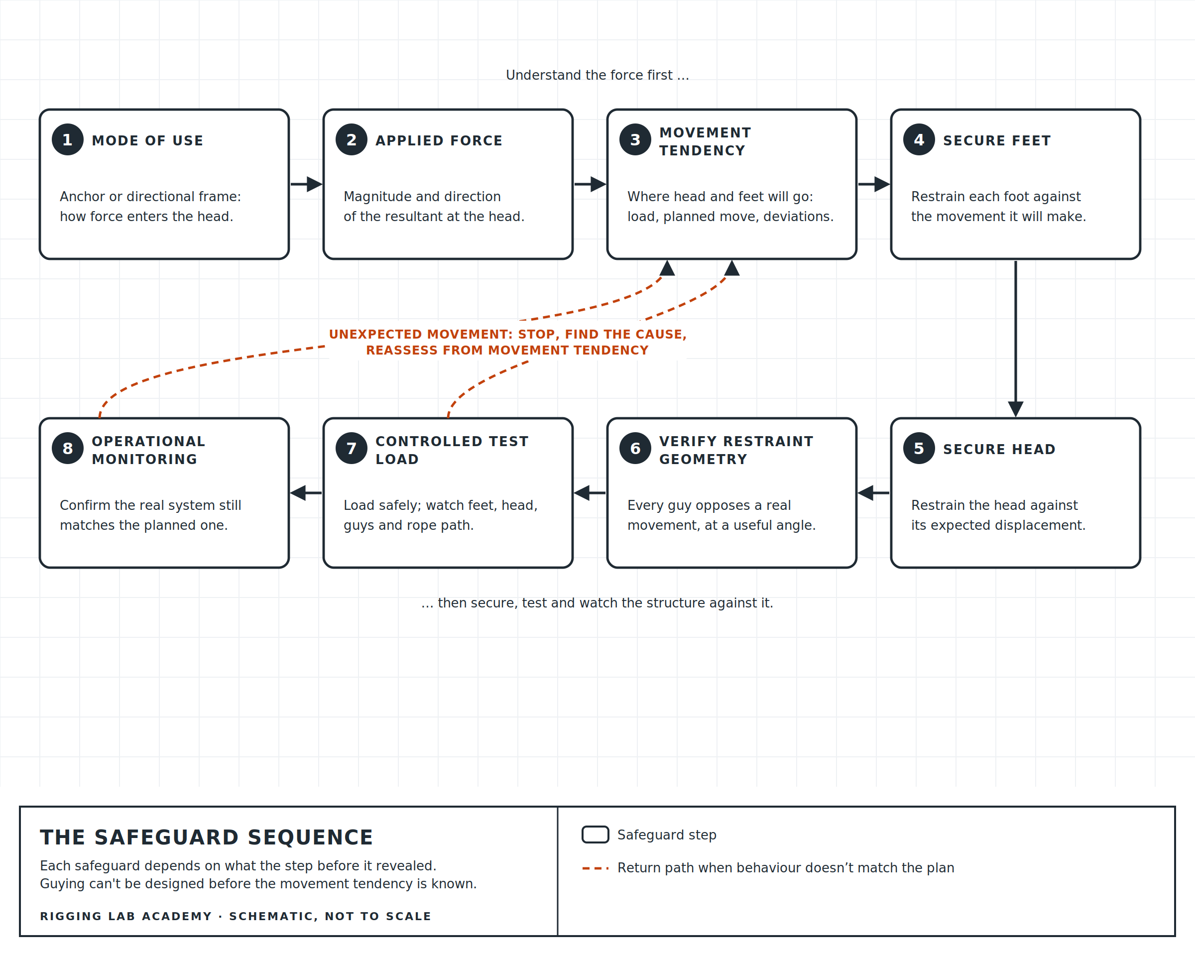
The safeguards in elevated-anchor work are most useful when they are understood as a connected sequence rather than as unrelated rules.
First, determine how the frame is being used. An Anchor Frame and a Directional Frame do not receive force in the same way.
Then determine the magnitude and direction of the applied force. Without that information, neither capacity nor stability can be evaluated correctly.
Next, determine the tendency of movement at both the head and feet. Consider the initial load, the planned movement, and foreseeable deviations.
The feet can then be secured against the movement they are expected to make, while the head is restrained against its anticipated displacement. Guy geometry is evaluated so the restraints actually provide useful opposition rather than simply adding more lines to the system.
Finally, the complete structure is test loaded and observed.
That sequence matters because each safeguard depends on the information produced by the previous one. Guying cannot be designed intelligently before the movement tendency is understood, and movement tendency cannot be predicted accurately before the applied force has been identified.
Safeguards Do Not Replace Monitoring
A properly secured and test-loaded frame still has to be watched during the operation.
The test confirms the conditions that were simulated. Once the load begins moving, rope angles may change beyond the initial test condition. A guy that carried little force initially may become more important. A foot may experience a different reaction. A structural high point may be loaded in a new direction.
This is where Lesson 5.4 and Lesson 6.3 meet.
Operational monitoring is the continuing safeguard that checks whether the real system still matches the anticipated system. Movement at the head, feet, restraints, anchors, rope path, or supporting structure provides information about what the forces are doing.
The system should remain predictable even though the load is moving.
Responding to an Unexpected Change
When an elevated-anchor system begins behaving differently from what was expected, the first priority is to prevent additional movement from making the condition more difficult to understand.
The rope system should be brought to a controlled condition whenever possible while the team identifies what changed. The observer then works through the load path: load position, rope path, head, legs or structural attachment, restraints, feet, anchors, and supporting environment.
The question is not simply, “What moved?” It is, “Why did it move?”
A foot may have shifted because the supporting surface failed to provide enough resistance. A guy may have slackened because the resultant changed direction. A head may have rotated because the working rope moved laterally. Increased hauling resistance may indicate unintended rope contact rather than additional load.
Correcting the visible symptom without understanding the cause can transfer the problem somewhere else. Tightening one guy, for example, may reposition the head and alter several other force relationships.
The system should return to operation only after the altered condition has been understood and the intended load path re-established.
Operational Scenario — A Small Change at the Edge
Consider an A-frame being used to raise a litter over an industrial parapet.
The frame has been assembled, its feet secured, the head guyed, and the complete system preloaded. During the vertical portion of the raise, the structure behaves as expected.
As the litter approaches the parapet, the load-side rope angle changes. At the same time, the edge attendant guides the litter several inches sideways to clear an obstruction. That movement introduces a lateral component that was not significant earlier in the raise.
The technician observing the frame notices a small rotation at the head and increased tension in one lateral restraint. The feet have not moved, but the frame is no longer carrying the load in exactly the condition established during preload.
The correct response is not to continue simply because the litter is nearly over the edge. Movement is controlled while the team confirms the rope path and the lateral position of the load. The package is brought back into the anticipated travel line, the head returns to its original orientation, and the restraint system again behaves as expected.
Nothing broke, and no component exceeded an obvious rating. Yet the team identified a developing failure condition because the load path began departing from the planned geometry.
That is the value of understanding failure before it becomes component failure.
System Integrity Is Maintained, Not Assumed
The safeguards developed throughout this course work together because elevated anchor systems are structural systems rather than collections of equipment.
Correct geometry establishes the load path. Hobbles, guys, and anchors preserve that geometry. Component inspection confirms that the structure can still perform as designed. Capacity limits keep the applied forces within acceptable bounds. Preloading tests the assembled system. Operational monitoring confirms that the system continues behaving as expected while the load moves.
Failure conditions develop when one or more of those relationships are lost.
The technician’s role is therefore not simply to recognize a collapsed or damaged frame. It is to recognize the earlier indicators that the system is beginning to depart from its intended structural condition and to correct or stop that process while control still exists.
That is the practical meaning of system integrity in elevated-anchor operations.
Peace on your Days
Lance