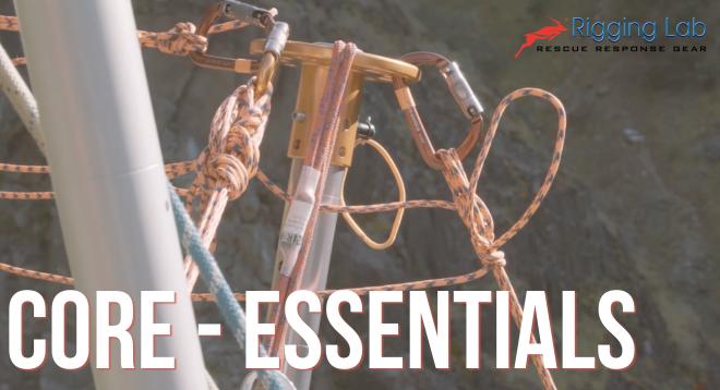
“How do you calculate potential force on a back tie? Today we rigged a leaning monopod setup. I did my best to keep my guy angle wider than my resultant angle, but I was wondering if there’s a way to estimate what the guy would see as they get closer to the same angle.” — @RLA Member
The instinct is right. Keeping the guy angle wider than the resultant angle reduces back tie force. But instinct doesn’t give you a number, and numbers are what anchor ratings and safety margins are built on.
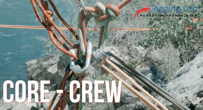
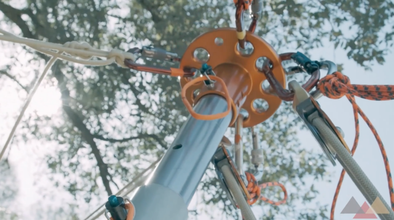
Three forces at the head
Any time a leaning monopod is loaded and not moving, three forces act on the head simultaneously and must sum to zero. Once you know two of them, the third is determined entirely by geometry.
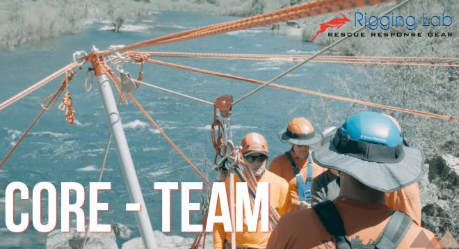
R — Applied load. The vertical force hanging from the head. For a freely suspended rescue load, this is your working load.
T — Back tie tension. The force your guy line is actually carrying. This is the number your anchor and hardware need to be rated for — and it can be significantly higher than the load at the head.
C — Pole compression. The axial load running through the pole from head to base. It consistently runs higher than back tie tension and catches a lot of riggers off guard.
Setting up equilibrium at the head and solving gives:
T = R × sin(α) / cos(α + β)
C = R × cos(β) / cos(α + β)
Where α is the pole lean from vertical and β is the back tie angle below horizontal.
The denominator — cos(α + β) — is what makes this geometry dangerous. As the combined angle approaches 90°, forces become unbounded. That’s the convergence Ben was asking about.
Reading the results
The force multiplier (T ÷ R) is the key output. A multiplier of 1.0 means the anchor is already seeing the full working load. At 2.0, it’s seeing twice that. Use this number to spec your anchor and verify hardware ratings.
The combined angle (α + β) drives the multiplier. You can trade lean for tie angle all day — what matters is the sum, not the individual values.
Don’t skip pole compression (C). It consistently runs higher than back tie tension. Verify the pole against the C value for your actual geometry.
What happens as the angles converge
The table below uses a horizontal tie (β = 0°) and 1,000 lb load. A horizontal tie gives the lowest possible back tie force — any downward tie angle pushes all values higher.
| Combined Angle | Back Tie Tension | Multiplier | Status |
|---|---|---|---|
| 10° | 176 lb | 0.18× | Favorable |
| 20° | 364 lb | 0.36× | Favorable |
| 30° | 577 lb | 0.58× | Manageable |
| 45° | 1,000 lb | 1.00× | Tie = Load |
| 60° | 1,732 lb | 1.73× | Elevated |
| 70° | 2,747 lb | 2.75× | High |
| 80° | 5,671 lb | 5.67× | Critical |
| 85° | 11,430 lb | 11.4× | Extreme |
| 89° | 57,289 lb | 57× | System Failure |
The jump from 60° to 80° in 20 degrees is the zone most field setups can actually reach. The climb isn’t linear — it accelerates hard as the denominator shrinks toward zero.
Field rules
- Keep the combined angle below 60%. That’s your anchor sizing floor. Below 45°, you’re in favorable territory on most setups.
- Run the tie as horizontal as possible. β = 0° is always the best geometry for a given lean. If terrain forces a steep tie, account for it explicitly.
- Size the pole against compression, not just the load. Pull the C value from the calculator for your specific geometry and verify it against your pole rating.
- The combined angle is the number to watch — not lean or tie independently. A 20° lean with a 50° tie is exactly as dangerous as a 50° lean with a 20° tie.
Want to go deeper on rigging vector math? The RLA course library covers anchor systems, mechanical advantage, and rope rescue rigging — same applied, field-first approach. Rigging Lab Academy