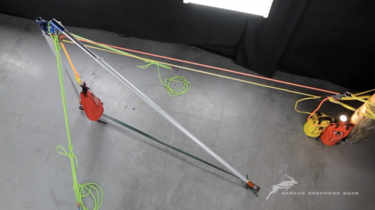
In technical rope rescue, the edge is often where a manageable rope system becomes difficult.
Ropes bend across abrasive surfaces. Friction increases. Mechanical advantage deteriorates. Attendants struggle to move a litter through the transition. Haul and lowering systems become harder to operate predictably, while the patient and rescuers remain exposed at one of the most consequential points in the operation.
An elevated anchor system changes that interface.
By raising the working rope path above an edge, opening, obstruction, or confined-space entry, an artificial high directional can create clearance, reduce unwanted rope contact, improve package movement, and establish a more usable relationship between the load and the operating system.
But an AHD is not stable simply because its legs are standing on the ground.
Its stability depends on geometry, force direction, foot restraint, guying, anchoring, configuration, and how all of those elements change as the load moves.
What Is an Artificial High Directional?
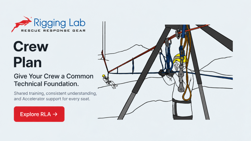
An artificial high directional, or AHD, is a manufactured structure used to elevate an anchor point or redirect a loaded rope system.
Common configurations include:
- Tripods
- Easel-leg tripods
- Bipods and A-frames
- Sideways A-frames
- Monopods or gin poles
A natural high directional accomplishes a similar purpose using an existing environmental or structural feature, such as a tree, rock formation, beam, or structural column. Unlike manufactured equipment, however, a natural feature does not arrive with standardized components or published configuration instructions. Its suitability must be established through inspection and competent structural judgment.
The distinction matters, but the governing question remains the same:
Where will the combined force acting on the elevated system ultimately go?
Elevation Is Only Part of the Objective
An AHD is often described as a way to “get the rope off the edge.” That is correct, but incomplete.
A properly selected and configured elevated anchor may provide several operational advantages.
Improved edge transitions
Raising the rope path can give the litter, patient, rescuer, or load room to move through the edge transition without being dragged directly across the lip.
Reduced rope contact
Eliminating or reducing contact with concrete, rock, steel, roofing, or structural edges can decrease abrasion exposure and reduce friction within the operating system.
Better system efficiency
A haul system may be theoretically correct but operationally inefficient because of bends, edge friction, pulley alignment, or equipment interference. Elevating the rope path can reduce those losses, although it does not eliminate the need to evaluate the complete system.
Controlled force direction
An AHD allows the rigging team to shape the rope path deliberately. This can make the direction of force more predictable—but it also means the team is responsible for understanding the forces created by that geometry.
The structure does not remove force. It receives and redirects it.
The Resultant Governs the Frame
Several individual forces may act on an AHD at the same time:
- The suspended or moving load
- The incoming rope tension
- The outgoing rope tension
- Pulley forces
- Guyline forces
- Hobble forces
- Reactions at each foot
- Resistance from the supporting surface
The resultant is the combined directional effect of the forces acting through the head of the frame.
That resultant is one of the principal indicators of how the structure will behave.
When the resultant is directed appropriately through the supported footprint, the legs can primarily function as compression members, transferring force from the head into the supporting surface.
When the resultant migrates toward or beyond the available support area, the frame may attempt to rotate, tip, lift a foot, spread, bend, or load components in a manner that the configuration was not intended to resist.
The Arizona Vortex manual repeatedly frames stability as a relationship between the resultant, the frame, the feet, and the supporting surface. It also requires the user to account for both the direction and magnitude of the forces present in the selected configuration.
This is why an AHD cannot be evaluated only while it is unloaded.
The load’s position changes. Rope angles change. A litter moves through the edge. A directional pulley may rotate. Guylines stretch or settle. Feet may shift on loose, sloped, or irregular terrain.
A system that appears stable during assembly may behave differently when operational force is introduced.
Anchor Mode and Directional Mode
The behavior of an AHD depends heavily on how it is being used.
Anchor mode
In anchor mode, the load or operating system is supported from the head of the structure. The force commonly acts generally downward, although its exact direction depends on the rigging arrangement and the position of the load.
Directional mode
In directional mode, a loaded rope passes through a pulley or other directional element attached to the frame.
The force applied to the frame is then influenced by both rope legs entering and leaving the directional. The resultant generally acts along the bisector of those rope tensions, assuming comparable tension on both sides of the pulley.
This distinction is critical.
A frame that is stable while supporting a vertically suspended load may behave very differently when used to redirect a rope through a substantial angle. The pulley does not merely “hold the load.” It transfers the combined effect of the loaded rope legs into the structure.
The rigging team must evaluate the actual rope path—not just the weight of the patient or package.
The Footprint Is a Working Boundary
For a tripod, the feet create a triangular support area. For an A-frame, the effective support area is much narrower. For a monopod, the pole itself offers almost no self-supporting footprint and depends extensively on external restraint.
The footprint should not be treated as a painted line on the ground. It is the result of:
- Foot locations
- Foot orientation
- Surface strength
- Friction
- Hobbling
- Anchoring
- Guying
- Frame geometry
- The direction of the applied force
A foot resting on compact soil behaves differently from one resting on loose gravel. A flat foot on concrete behaves differently from a toothed foot engaging rock. A foot near an edge, trench, void, roof seam, or deteriorated surface may have little usable support even though it appears physically inside the frame.
The operational question is not simply, “Are the feet spread apart?”
It is:
Can every contact point resist the forces that this configuration may place upon it?
Hobbling, Guying, and Foot Restraint Are Not Interchangeable
AHD stabilization is usually created through several different mechanisms. Each solves a different problem.
Hobbling
Hobbling connects the feet to prevent the legs from spreading outward under compression.
It preserves the geometry of the base, but it does not automatically prevent the entire frame from tipping, translating, or rotating.
Foot restraint
Feet may need to resist:
- Spreading
- Sliding
- Side loading
- Rotation
- Uplift
- Movement toward the edge
The current Arizona Vortex manual requires the feet to be secured against sideways, spreading, and uplift forces. The appropriate method depends on the selected feet, surface, frame configuration, and expected load direction.
Guying and back-ties
Guylines provide external restraint against movement that the frame’s footprint alone cannot reliably control.
Their anchor locations should oppose the actual anticipated movement of the structure. Adding guylines in convenient directions does not necessarily stabilize the frame if they do not resist the resultant’s tendency.
A guyline also introduces its own force into the system. Poor guy geometry may create high anchor loads, excessive compression, side loading, or opposing forces that make the frame difficult to evaluate.
The objective is not to surround the AHD with rope.
The objective is to establish a deliberate system of restraints that holds the frame in its intended geometry throughout the operation.
Tripods: Stable Geometry With Important Limits
The equal-leg tripod is the most familiar high-directional configuration.
With three appropriately placed feet and a load suspended within the supported area, it can provide a comparatively broad and stable footprint. That does not make every tripod setup inherently safe.
The load should not be allowed to swing uncontrolled toward a side of the structure. The feet must remain restrained, and the head must not be subjected to unanticipated horizontal loading.
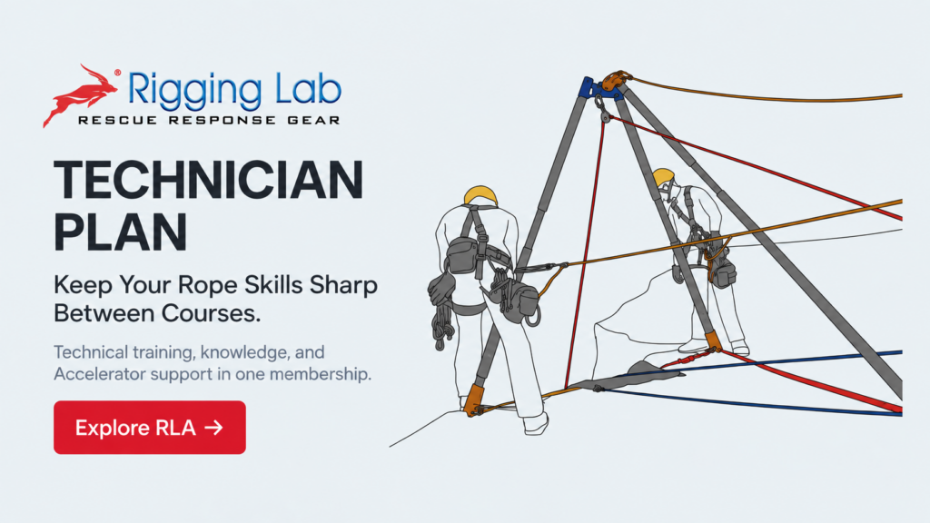
An easel-leg tripod uses two legs as an A-frame and a third leg as an additional support or stabilizer. Its asymmetrical geometry makes it adaptable to edges and openings, but its behavior must be evaluated according to the direction of the resultant.
Depending on whether it is being used as an anchor or directional frame, the structure may tend to move toward the edge, away from the edge, sideways, or around one of its feet.
The third leg is not automatically a complete substitute for guying.
Bipods and A-Frames: Efficient but Directionally Sensitive
An A-frame provides elevation through two legs and a narrow base.
This can make it extremely useful at a parapet, cliff edge, shaft, industrial opening, or confined work area. It also means that it has far less independent resistance to movement outside the plane of the frame.
A conventional A-frame commonly requires restraints on both sides of the frame to prevent forward or rearward rotation.
A sideways A-frame turns the frame relative to the primary load path. This may be useful when the available anchors are located to the sides or when the operating area does not permit conventional front-and-rear guying.
The configuration must still be evaluated as an entire force system. Turning the frame does not eliminate the resultant; it changes the way the legs, feet, and restraints receive it.
Monopods and Gin Poles: Maximum Flexibility, Minimum Inherent Stability
A monopod provides elevation through a single compression member.
It has no self-supporting footprint comparable to a tripod or bipod. Its stability is created by the relationship between the foot, head, load, and guying system.
This makes the monopod useful in confined or irregular locations—but also highly dependent on rigging discipline.
The guylines must hold the pole in the intended plane and oppose movement in every credible direction. The foot must be secured against translation and uplift, and the head must be controlled against rotation.
Some rigging practices deliberately position the pole slightly toward the anticipated loaded direction before final tensioning. The purpose is not to guarantee “perfect alignment.” It is to account for expected settling, stretch, and movement as the system is loaded.
That adjustment must be based on the specific frame, instructions, configuration, and observed system behavior—not a universal lean angle.
The Arizona Vortex as an Applied AHD System
The Arizona Vortex is a modular multipod designed for tripod, bipod, easel-leg, sideways A-frame, and monopod configurations.
Its headset allows multiple structural arrangements and permits pulleys to be connected directly to the head in certain configurations, reducing lost headspace. The manufacturer describes the unit as a portable anchor device and artificial high directional intended for trained users working in rescue, rope access, and technical rigging environments.
Headset and leg pins
The manufacturer lists two principal pin sizes:
- 3/8-inch leg pins: 18,000 lbf, or 80 kN
- 1/2-inch head pins: 32,000 lbf, or 142 kN
Those values are component pin-strength specifications. They should not be interpreted as the working capacity of every assembled frame or configuration. Overall system capacity depends on configuration, force direction, component placement, leg extension, guying, foot conditions, and the manufacturer’s operating limitations.
Every pin must be fully inserted and positively engaged. Pin count is not a substitute for inspection. The team must visually and physically confirm that each locking mechanism is functioning before the system is loaded.
Raptor and flat feet
Raptor feet are intended to gain purchase on irregular or penetrable surfaces.
Flat feet distribute force over a larger area and are commonly used on hard, smooth surfaces such as concrete, pavement, roofs, and industrial flooring. Foot selection must account for both the surface and the direction of expected loading.
A foot should never be assumed secure solely because it sits flat.
Its ability to resist compression, sliding, side load, rotation, and uplift must be considered independently.
AHDs in Offset Systems
An offset moves a suspended package away from a direct vertical path.
An AHD may be used to elevate one or more stations, improve clearance, or shape the track and control-line geometry.
The force on the structure changes as the package moves. The track-line angle, control-line direction, and load position may all shift during the operation. The most demanding condition may occur near a station, during a transition, or when one portion of the system becomes disproportionately loaded.
A deep sag generally produces lower horizontal anchor forces than a flat, highly tensioned span. However, no single sag angle can be applied universally. The proper geometry depends on the span, load, available clearance, anchor capacity, operating method, and the equipment being used.
The AHD must be evaluated throughout the package’s intended travel—not at one convenient point in the system.
AHDs in Highline Systems
Highlines place substantial responsibility on anchors, track lines, control systems, and supporting high directionals.
As a tensioned span is flattened, the horizontal forces at its anchors increase rapidly. This fundamental behavior is why highly tensioned, low-sag systems require disciplined force analysis and strict operating limits.
AHDs may provide the elevation needed to maintain clearance and support the required rope geometry, but they also become part of the loaded structure.
A highline station should therefore be evaluated as one integrated system:
- Main anchors
- Track lines
- Control lines
- Haul and lowering systems
- High directionals
- Guylines
- Feet and supporting surfaces
- Backup and consequence-management systems
The AHD is not an accessory placed beside the highline. It is one of the structures through which the highline forces are resolved.
Standards, Equipment, and Technician Competency
Older training materials frequently refer separately to NFPA 1670 for technical-rescue operations and NFPA 1983 for life-safety rope and equipment.
Those documents were consolidated into NFPA 2500, which addresses technical search-and-rescue operations and training as well as life-safety rope and equipment. References to the older numbers may remain relevant when discussing legacy editions, older equipment labels, or organizational documents, but they should not be presented as the current independent standards without that context.
NFPA professional-qualification material identifies the ability to assemble and stabilize a high-directional rope-rescue system, understand resultant forces, apply guylines, assess load distribution, and complete system safety checks as rope-rescue competencies. It does not mean that a technician can safely operate every proprietary AHD after reading a general standard or manual.
Manufacturer instructions, organizational procedures, documented training, and hands-on competency remain essential.
Build, Restrain, Test, and Observe
Before an AHD is committed to a live rescue load, the system should be inspected and test-loaded in a controlled manner.
The test is not ceremonial. It is an opportunity to observe whether the actual system behaves as predicted.
The team should watch for:
- Foot movement
- Leg spreading
- Head rotation
- Guyline imbalance
- Anchor movement
- Surface failure
- Component interference
- Pulley misalignment
- Pin displacement
- Unexpected flexing or settling
- Resultant migration as the load moves
Some initial seating may occur as components and restraints take load. Continued movement, progressive settlement, foot lift, uncontrolled rotation, or changing guy tension indicates that the frame is not behaving as intended.
The operation should stop until the cause is understood and corrected.
The AHD Must Be Managed as a System
An artificial high directional does not make a rope-rescue system safer merely by adding height.
It creates a new structure that must receive, redirect, and transfer force into the ground and surrounding anchors.
The real discipline lies in understanding the complete load path:
- From the patient or load
- Through the rope system
- Into the directional or anchor point
- Through the frame
- Into the feet, guylines, anchors, and supporting surface
When that path is deliberate, restrained, tested, and continuously observed, an AHD can turn a severe edge into a controlled working interface.
When the geometry is misunderstood, the same structure can introduce movement, instability, and force into locations the rigging team did not anticipate.
The equipment matters.
The configuration matters more.
And the final measure of the system is not how it looks before loading—but how predictably it behaves once the operation begins.
Peace on your Days
Lance