Technical Operational Rigging: Seeing the Entire System
Technical Operational Rigging brings together skills that are often learned separately. Anchors, mechanical advantage, twin tension systems, directionals, highlines, Artificial High Directionals, system transitions, and contingency planning all have their own techniques and terminology, but an advanced rescue operation requires them to function as parts of the same system.
That changes what the rigger has to pay attention to. Knowing how to build an anchor or assemble a mechanical advantage system remains important, but the larger task is understanding how force moves through the entire rigging arrangement. A change in rope angle can alter anchor loading. A directional can improve the rope path while introducing another resultant force. Friction can reduce the actual performance of a haul system. A transition from lowering to raising can create a control problem if that transition was not considered during the initial setup.
The Technical Operational Rigging Study Guide is built around that systems-level understanding. Its purpose is to bring vector analysis, mechanical advantage, tension systems, load-path evaluation, redundancy, system transitions, and contingency planning into one operational framework. The emphasis is not simply on recognizing equipment, but on understanding why the system behaves as it does and anticipating what will happen as conditions change.
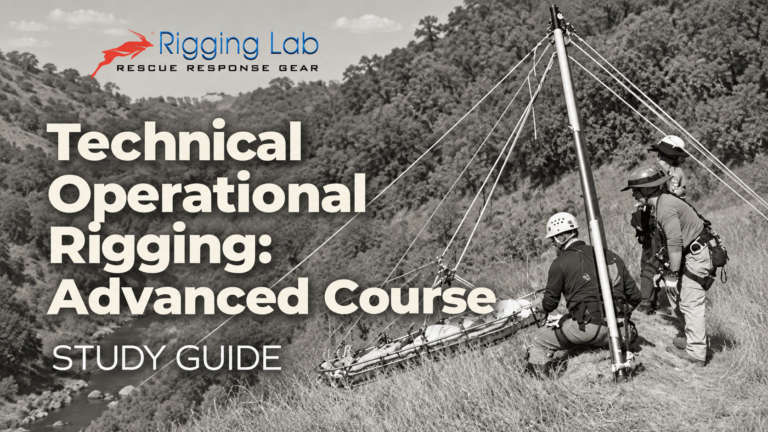
Technical Operational Rigging: Advanced Course Study Guide
Use the Study Guide to work through the force relationships, system interactions, transitions, and contingency concepts covered throughout this article.
Get the Study Guide
Follow the Force Through the System
A component inspection tells us something important about the equipment, but it does not tell us what the complete system will do under load. System-level analysis begins by tracing tension from the load through every rope segment, pulley, directional, device, anchor leg, and final attachment point.
That distinction becomes especially important when geometry changes. In a multi-point anchor, widening the angle between the legs increases the force carried by each leg. The Study Guide uses this relationship to illustrate why vector management is part of anchor design rather than a separate mathematical exercise. At 60 degrees each leg carries more than half of the applied load. At 90 degrees the force rises further, and at 120 degrees each leg is carrying the equivalent of the full applied load. Beyond that point, each leg can be carrying more force than the suspended load itself.
The same reasoning applies when a rope changes direction. A directional pulley does more than improve the working position of a rope. The incoming and outgoing rope tensions combine at the directional anchor and create a resultant force. In the Study Guide’s 90-degree deviation example, that resultant is approximately 1.41 times the line tension. The directional has therefore become its own load-bearing point and has to be evaluated accordingly.
This is the practical value of load-path analysis. The rating printed on a component remains important, but the more useful operational question is what force is actually reaching that component and from what direction. That requires the rigger to account for the geometry surrounding the equipment rather than evaluating the equipment by itself.
Redundancy Has to Exist at the System Level
Redundancy can also be misunderstood when it is evaluated one component at a time. Two ropes, two devices, or several connectors may create duplication without creating meaningful independence.
The Two-System Approach described in the Study Guide treats redundancy as a relationship between complete systems. Separate anchorage is part of that design, but the same idea extends through the rope paths and the way the systems are operated. If both systems depend on the same vulnerable structure, travel across the same damaging edge, or share another critical failure point, one event may compromise both systems at the same time.
This is why common-mode failure matters. A second system is valuable only if it remains functional when the first system has a problem. That requires the crew to look beyond duplicated hardware and examine what the two systems actually have in common.
Twin Tension Systems extend that reasoning into active load control. Both ropes remain tensioned and participate in supporting the load rather than placing the entire working load on one rope while another remains comparatively passive. The two systems still require appropriate independence, but they operate as a coordinated pair. Equalized operation reduces the amount of uncontrolled movement that would otherwise occur if a slack system suddenly had to assume the load.
The important point for Technical Operational Rigging is not to repeat the entire Twin Tension curriculum. It is to understand why TTS belongs inside the larger system architecture. Redundancy, load sharing, operator coordination, anchor independence, and transition planning all have to work together. A weakness in one of those areas changes the behavior of the whole operation.
Geometry Is Part of Operational Control
Horizontal systems make the relationship between geometry and force particularly clear. As sag decreases and the line becomes flatter, the tension required to support the load increases rapidly. The system may look cleaner or tighter, but the anchors are being asked to resist greater forces. The Study Guide uses highline behavior to reinforce the broader principle that rope geometry directly controls the loads transmitted into the system.
That same relationship appears in other forms throughout advanced rigging. Changing the location of a directional changes the rope angles around it and therefore changes the resultant acting at that point. Changing an anchor-leg angle changes the loading carried by those legs. Raising or lowering a working point on an Artificial High Directional changes the relationship between the rope path, the frame, and the anchors supporting it.
Artificial High Directionals are useful because they can create a cleaner path around an edge, reduce unwanted rope contact, and position the load where it can be moved more effectively. They also change the force map of the system. The rigger has to evaluate the AHD as part of the load path rather than as an isolated support structure.
Taglines provide another example of separating functions within the same operation. The primary rope systems manage the main load and vertical movement, while the tagline provides directional control. Used that way, the tagline can stabilize a litter, help control rotation, maintain obstacle clearance, or influence horizontal position without replacing the primary load-bearing system.
These systems demonstrate why an advanced rig cannot be evaluated only in its initial position. The important geometry may continue to change after the load starts moving. The rigger therefore has to consider the expected range of travel and determine how rope angles, resultants, anchor loading, friction, and clearances will change through that movement.
Plan the Transition as Part of the Initial Rigging
Some of the most demanding moments in a rope rescue occur when the operation changes from one mode to another. A controlled lower may have to become a raise. A mechanical advantage system may have to be added or removed. A load moving vertically may have to transition into another plane of movement.
A transition can create additional exposure because tension and control are being transferred between functions. If the system has to be dismantled or substantially reconstructed before the new operation can begin, the crew has created a period in which several things have to be managed correctly while the load remains present.
The Study Guide treats transition readiness as a design issue rather than something to solve after the need arises. Multi-purpose devices such as the MPD and Clutch are used as examples because lowering control and progress capture can be incorporated into the same operating platform. A team can prepare a system so that mechanical advantage can be introduced while the primary rope remains controlled, allowing the operation to change direction without rebuilding the entire load path.
The equipment is useful, but the larger principle is more important. The original system should anticipate the transitions that are reasonably likely to occur during the rescue. If lowering is the initial plan but raising remains a realistic possibility, the system can be arranged so that the change does not require unnecessary disconnecting, rethreading, or transfer of control.
Integrated components can help support that approach when they simplify alignment and reduce unnecessary connectors or handling. The Study Guide’s discussion of the Petzl SPIN pulley, for example, uses the integrated swivel as an illustration of equipment design that assists orientation and directional control. The significance is not the product itself; it is the effect that alignment and simplified hardware relationships can have on the larger system.
Continue with the Technical Operational Rigging Study Guide
The Study Guide carries these relationships into the complete advanced course, including force analysis, system transitions, TTS, directional loading, failure analysis, and releasable rigging.
Get the Study Guide
Mechanical Advantage Has an Ideal Value and an Actual Value
Mechanical advantage is another area where system thinking changes the analysis. Theoretical Mechanical Advantage describes what the pulley and rope arrangement should produce under ideal conditions. It gives the rigger the structural relationship between input force and output force and remains the starting point for understanding the haul system.
The operating system adds friction.
Rope bends around hardware. Pulleys have mechanical losses. Progress capture devices add resistance. The rope may contact terrain or an edge. Poor alignment can increase drag through pulleys and devices. Each of those effects reduces the force that ultimately reaches the load.
The Study Guide separates Theoretical Mechanical Advantage from Actual Mechanical Advantage for this reason. TMA describes the ideal configuration, while AMA describes the performance the system actually provides once real friction and hardware interaction are included. The guide identifies friction, pulley efficiency, rope path, device resistance, and alignment as factors that can reduce actual performance.
This has a direct operational consequence. A haul that feels heavier than expected does not automatically require another layer of mechanical advantage. The system may first need to be examined for unnecessary rope bends, a poorly placed redirect, excessive edge friction, device resistance, or misalignment. Adding more pulleys to an inefficient arrangement can increase complexity while leaving the underlying source of resistance in place.
Actual performance can also be measured. Load cells and tension meters allow the crew to compare expected forces with what the system is producing under load. That information turns friction from an assumed loss into something that can be observed and used to refine system design.
The larger lesson is consistent with the rest of Technical Operational Rigging. The diagram explains the intended behavior, but the operating system has to be evaluated as it actually exists.
Failure Analysis Begins Before the Load Is Committed
Advanced system analysis also includes the possibility that a component, procedure, or human interaction will not behave as expected. Failure Modes and Effects Analysis provides a structured way to examine that problem before the system is placed under a live load.
The Study Guide uses FMEA as a predictive process. Rather than limiting inspection to whether individual components appear serviceable, the analysis considers potential failure modes across hardware, rope paths, procedures, and human interfaces. The next step is to consider what each failure would do to the rest of the system and which failures require a design or procedural response before operation begins. The Study Guide places FMEA alongside contingency rigging and releasable-system design as part of managing uncertainty in advanced operations.
That system-level consequence is important. A pulley problem may do more than remove one pulley from service if its failure changes the load distribution somewhere else. A missed step during a load transfer may produce consequences beyond the device being operated. Ambiguous communication can become a system hazard if two operators make incompatible movements at the same time.
FMEA therefore connects technical analysis with human factors. Hardware, procedures, communication, and system interfaces are all capable of affecting the load path. The useful outcome is not simply a list of possible failures. The analysis should change the system, the procedure, or the contingency plan where a credible failure would otherwise leave the operation without an acceptable response.
Releasable Systems Preserve Options Under Load
Contingency rigging builds on that failure analysis by preserving controlled options after the original plan has been disrupted.
A static system can be very secure while everything proceeds exactly as expected. The problem appears when the load is fully committed and some part of the planned operation can no longer continue. A mechanical advantage system can become unusable, the direction of movement may need to reverse, or a section of the load path may need to be transferred.
Releasable-system design addresses that condition by allowing a loaded pathway to be deliberately managed rather than simply locked in place. Devices with friction control can provide the means to lower under load, transfer tension, or support a controlled change in operating mode without surrendering positive control.
This is closely related to transition readiness. A system that can change from lowering to raising and back again without complete reconstruction is easier to adapt when circumstances change. The same architecture that makes routine transitions cleaner can also provide useful options during a contingency.
The requirement remains control. Releasable does not mean uncontrolled movement, and contingency does not mean abandoning the original system principles. The anchor structure, force path, redundancy, and human operation still have to remain understandable while the change takes place.
Simplicity Depends on Understanding
Advanced rigging can easily accumulate equipment. Additional devices, redirects, mechanical advantage, and backup arrangements can all serve legitimate purposes, but each one also adds another relationship that has to be understood and operated.
The Study Guide approaches minimalist and improvised rigging from that perspective. The value is not in using less equipment for its own sake. It is in understanding the governing principles well enough to preserve force control, redundancy, and system resilience when the ideal arrangement or full equipment package is not available.
A simpler rig is still governed by the same force relationships as a more elaborate one. Anchor geometry still changes the load carried by the anchor legs. Mechanical advantage still has friction losses. Directionals still create resultants. A reduced system still has to maintain appropriate redundancy and retain control during a failure or transition.
This is why improvisation has to remain principle-driven. Removing equipment without understanding what function it was performing is not simplification. It is simply removing part of the system. Effective simplification retains the functions necessary for the operation while reducing unnecessary complexity.
That becomes particularly valuable when time, space, personnel, or equipment are limited. The rigger is no longer dependent on reproducing one preferred arrangement exactly. The underlying relationships provide the basis for adapting the system while keeping its behavior predictable.
Human-Centered Design Is Part of Rigging Design
The rescue system is operated by people, so system reliability depends partly on how easily those people can understand and use what has been built.
A technically capable system can still become difficult to operate if the rope path is confusing, device orientation is inconsistent, commands are ambiguous, or transitions require a long sequence of precise actions. Those issues increase cognitive demand at the same time operators may already be managing communication, changing conditions, patient movement, and system forces.
The Study Guide treats human-centered design as part of the technical system rather than as an administrative concern. The principle is to make correct operation clear and intuitive while making incorrect operation difficult or obvious. It places this alongside friction management, transitions, FMEA, and releasable rigging because human interaction is another part of overall system behavior.
Clean rope paths make visual verification easier. Consistent equipment placement reduces the amount of interpretation required at a workstation. Standardized commands allow operators to coordinate changes without inventing language during the operation. Functional consolidation can reduce the number of handoffs required when the load changes direction.
These choices do not eliminate the need for training or attention. They reduce unnecessary dependence on perfect human performance. A system that communicates its own arrangement clearly is easier to inspect, easier to operate, and easier for another trained team member to understand.
Technical Operational Rigging Brings the Disciplines Together
Anchors establish the foundation of the system. Mechanical advantage determines how input effort is transformed into movement. Twin Tension Systems address active load sharing and redundancy. Horizontal systems bring sag, span, and high tension into the force analysis. Artificial High Directionals change the rope path and allow the system to work around difficult edges and obstacles.
Technical Operational Rigging brings those subjects together because none of them operates independently once a rescue load starts moving.
The anchor affects the mechanical system attached to it. The mechanical system changes the tension in the rope. A directional changes where that tension is applied. Friction changes the amount of force transmitted through the system. A transition changes which components are controlling the load. The contingency plan determines what options remain when one part of that arrangement no longer behaves as expected.
The advanced level is therefore less about adding another collection of techniques than about developing a dependable way to evaluate the complete operation. The rigger has to understand the forces present, the geometry producing them, the effect of friction, the independence of the redundant systems, the anticipated movement of the load, the transitions required during that movement, and the consequences of credible failure modes.
That systems-based reasoning is the central purpose of the Technical Operational Rigging Study Guide. It is intended to move the learner beyond recognizing rigging components and toward understanding how the system behaves, why it behaves that way, and how to maintain controlled adaptability throughout the operation.
Technical Operational Rigging: Advanced Course Study Guide
Use the complete Study Guide to continue working through the force analysis, redundancy, mechanical advantage, transitions, human factors, FMEA, and contingency principles that make up advanced Technical Operational Rigging.
Get the Study Guide
Peace on your Days
Lance