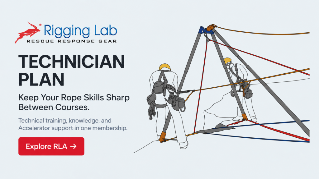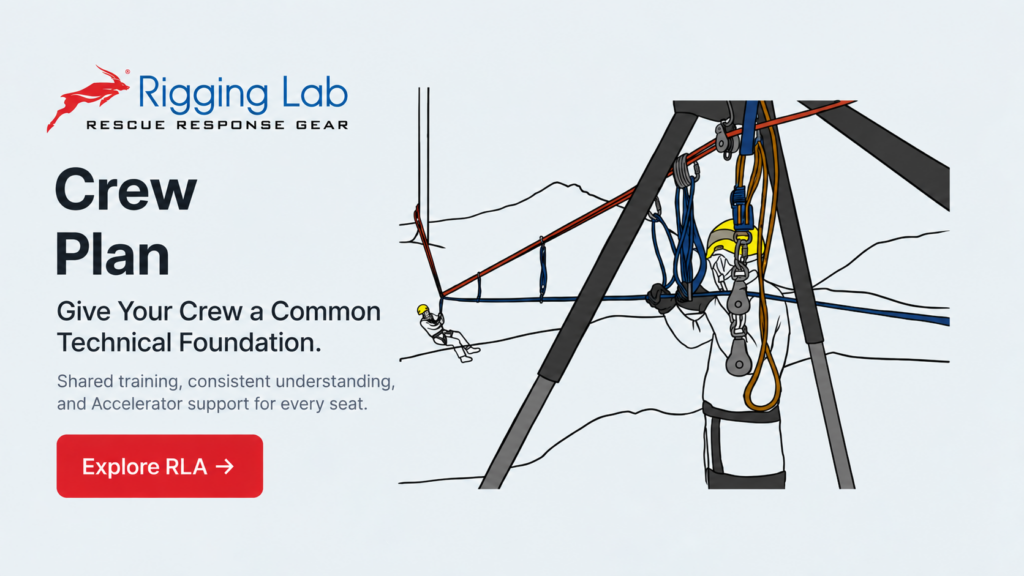

In rope rescue, mechanical advantage and anchor systems are never separate subjects. Every haul system depends on an anchor, and every anchor must be capable of resisting the forces a mechanical advantage system creates. That relationship is often misunderstood. Rescuers may focus on the efficiency of a 3:1 or 5:1 system, yet overlook how redirects, pulley placement, anchor geometry, and tension flow can increase the forces carried by the anchor itself. Understanding this relationship is foundational to safe system design.
This three-lesson study explores how mechanical advantage and anchor systems work together as one integrated force path. Beginning with force flow through mechanical advantage, moving into anchor geometry and load distribution, and concluding with anchor design for specific MA configurations, the progression helps students move beyond memorizing ratios toward understanding how systems behave under load. Whether evaluating a simple Z-rig or building more complex haul systems, this study develops the reasoning needed to connect mechanical advantage to the anchors that hold it.
Lesson 1
Force Flow Through Mechanical Advantage Systems
Mechanical advantage does not make force disappear. It changes where force travels, how it concentrates, and what the anchor system must ultimately resist. A haul team may feel the benefit of a 3:1 system at the rope, but the anchor may still be receiving the load plus additional forces created by pulleys and redirects.
The key concept is force tracing. The T-Method assigns one unit of tension to the haul line and follows that tension through the system. This allows the rescuer to see that a 3:1 Z-rig can place 2T on the change-of-direction pulley at the anchor. As MA increases, anchor demand also increases. A 5:1 system may create 6T at the anchor, depending on configuration.
Key learning points:
- Mechanical advantage redistributes force rather than eliminating it.
- A 3:1 Z-rig can place 2T on the anchor-side change-of-direction pulley.
- Larger MA systems can create larger anchor loads.
- The T-Method is the primary tool for predicting anchor force.
Primary source:
https://rigginglabacademy.com/courses/03-mm-mainline-rope-rescue-systems/lessons/force-dynamics/
Lesson 2
Anchor Geometry and Load Distribution
Anchor strength is not determined only by the quality of the anchor points. Geometry controls how force is shared, multiplied, or concentrated. Wide anchor angles increase force in each leg, and when that geometry supports a mechanical advantage system, the consequences become more serious.
A 120-degree anchor angle can place 100 percent of the load on each anchor leg. Beyond that, forces can increase rapidly. The same problem appears in directional redirects. A 90-degree redirect can place 141 percent of the load on the redirect anchor. When that redirect is part of an MA system, the anchor must be evaluated as part of the whole force path, not as an isolated attachment point.
Key learning points:
- Anchor angles should remain below 90 degrees when possible.
- A 60-degree angle is the preferred field standard.
- Directional pulleys create resultant forces at the anchor.
- Equalization helps distribute force across multiple anchor points.
- Poor geometry combined with MA can overload an otherwise acceptable anchor.
Primary source:
https://rigginglabacademy.com/courses/02-video-mechanical-advantage-and-force-multipliers/lessons/envision-your-anchor-systems/
Lesson 3
Building Anchors for Specific MA Configurations
Every MA system needs an anchor designed for the forces that system creates. The anchor must be evaluated against the theoretical advantage, the change-of-direction forces, the direction of pull, and real-world friction. A 3:1 system may require an anchor capable of holding at least 2T at the directional pulley. A compound 6:1 system can demand anchors capable of resisting 6T.
Adjustable load-sharing anchors can help manage alignment. A non-working 3:1 anchor adjustment system allows micro-tensioning so the focal point can be aligned with the pull direction. This helps keep the resultant vector inside the anchor footprint and prevents unintended force concentration.
Key learning points:
- Anchor design must match the specific MA configuration.
- The T-Method should be used before the system is loaded.
- Compound systems multiply lifting power and anchor stress.
- Adjustable anchors can help maintain focal point alignment.
- The anchor must be evaluated as part of the full system, not as a separate component.
Study Progression Summary
This study moves from force behavior, to anchor geometry, to system construction. The central lesson is simple: mechanical advantage and anchors cannot be studied separately. The MA system creates the force pattern, but the anchor system must survive it.
Peace on your Days
Lance