Anchor Force Distribution in Technical Rescue Rigging
Understanding anchor force distribution in technical rescue is the difference between a technician who follows rules and one who understands why those rules exist. This tool makes that understanding tangible — not through charts or formulas alone, but through live, interactive geometry that responds to your input and shows you exactly what happens to anchor loads as conditions change.
What the tool is
The Anchor Force Calculator is an interactive, browser-based educational tool with two calculators. Neither is designed for field use. Both are designed to do something that static diagrams and written rules cannot: let you change a variable and immediately see what happens to the forces involved. That cause-and-effect relationship — felt through direct manipulation rather than read off a chart — is what builds genuine understanding.
The two calculators address the two most common anchor force problems in technical rescue.
Calculator One: Two-Point Anchor Force
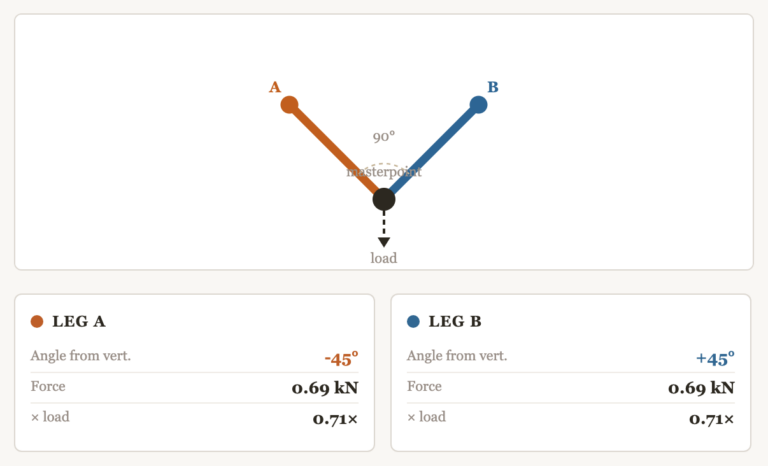
The two-point anchor is the foundation of rescue rigging. Two legs meet at a masterpoint. The load hangs below. The question every technician needs to be able to answer — not just recite, but actually understand — is: how much force is each leg carrying, and what controls that?
The answer is geometry. Specifically, two things: the angle between the legs at the masterpoint, and whether those legs are symmetric or not.
This calculator lets you set each leg independently. Leg A has its own slider. Leg B has its own slider. This is deliberate — because in real rescue environments, legs are almost never symmetric. Your left anchor might be at 30 degrees from vertical. Your right anchor might be at 55 degrees. The forces on those two points are completely different, and a rule of thumb built around symmetric geometry will mislead you.
As you move the sliders, three things happen simultaneously. The visual diagram updates — the legs visually thicken in proportion to the force they’re carrying, so you can see at a glance which anchor is doing more work. The leg detail cards update with the exact force in kilonewtons and the multiplier relative to the suspended load. And the status bar tells you which zone you’re in.
The three zones are built around defensible thresholds. Below 120 degrees, forces are within normal range. Between 120 and 140 degrees, you’re in the caution zone — each leg is now carrying more than the full load weight, and your safety margin is being consumed. Above 140 degrees, the system is in the critical zone. At 140 degrees, even in symmetric geometry, each leg carries 131 percent of the load. Add dynamic loading from a moving or agitated patient — which rescue systems regularly experience — and anchor forces can exceed ratings before anything looks wrong.
The 140-degree critical threshold is not arbitrary. Rescue systems operating under life-safety loads are designed to a 10:1 safety factor. At 131 percent per leg, that margin is being consumed by geometry alone, before any dynamic multiplier is applied. This is why instructors teach 120 degrees as the caution line: it gives you room before the math gets dangerous.
One additional behavior worth noting: if a leg is dragged past 60 degrees from vertical, the diagram begins showing it as dashed and faded. Past 75 degrees, a warning appears. This is because a nearly horizontal leg is not functioning as an anchor leg in any meaningful sense — it is acting as a redirect. Its cosine contribution to vertical support approaches zero. The math still produces numbers, but those numbers are misleading if you don’t understand what the geometry is actually doing. The visual flag is there to make that visible.
Calculator Two: Redirect (COD) Pulley Anchor Load
The change-of-direction pulley — COD, redirect, running pulley, whatever your agency calls it — is one of the most misunderstood pieces of hardware in rescue rigging. Technicians often assume the anchor holding the pulley only needs to be rated for the load being moved. This is wrong, and the consequences of that misunderstanding are serious.
The anchor holding a redirect pulley sees the vector sum of both rope segments passing through it. That is always greater than the load weight alone — sometimes dramatically so.
At zero degrees, where the incoming and outgoing rope are parallel and running in the same direction, the anchor sees 200 percent of the system load. Both rope tensions add directly. At 90 degrees — a common redirect configuration — the anchor sees 141 percent. At 170 degrees, where the ropes are nearly opposing each other, the tensions largely cancel and the anchor load drops to around 17 percent.
The diagram makes this physics visible in a way that a formula cannot. You can see the pulley. You can see both rope segments leaving it — one toward the load, one toward the haul team. As you change the angle between them, the sling connecting the pulley to its anchor changes color: green for low load, yellow for moderate, red for high. The force label on the sling tells you exactly what that anchor is experiencing as a multiplier of the suspended weight.
This is not intuitive. Technicians who have never worked through this calculation often underestimate COD anchor requirements by a significant margin. Seeing the geometry move — watching the anchor load climb as the rope angle tightens — creates an understanding that sticks.
Why this matters for technicians
Anchor failure in rescue is not usually the result of a single catastrophic mistake. It is usually the result of accumulated small errors — a slightly too-wide angle, a leg that was shallower than it looked, an anchor rated for the load weight rather than the actual force on it. Each individual error might be within tolerance. Together, they are not.
Technicians who understand force distribution make better decisions under pressure. They recognize when a geometry is drifting toward a caution zone before it gets there. They know which anchor point is governing the system and verify that one first. They understand why the 120-degree rule exists, which means they apply it correctly even when the geometry doesn’t look like the textbook diagram.
That is the purpose of this tool. Not to replace field judgment — nothing replaces field judgment — but to build the conceptual foundation that makes field judgment reliable. Play with the angles. Watch what happens to the forces. Notice how quickly things change as geometry becomes unfavorable. That intuition, built here in an academic setting, is what carries into real operations.
All forces are calculated using static equilibrium. Dynamic multipliers from patient movement, shock loads, or mechanical advantage systems are not included — those are additional factors that only compound what this tool shows. The tool uses a 10:1 safety factor standard consistent with NFPA technical rescue guidelines. All calculations are for educational purposes. Always verify system design with a qualified rigging assessment.
Peace on your Days
Lance