Rigging a 5:1 MA Off a Tripod for Confined Space Rescue
A complete operational breakdown for raising a 200 lb load 30 feet — with limited anchor geometry and edge protection requirements.
A 5:1 mechanical advantage system off a tripod is one of the most reliable configurations for vertical confined space extraction — but only when the geometry is right. Get the resultant vector wrong, and the tripod tips before the load clears the opening.
01 — Pre-Rig Assessment
Map your anchor points first
Before the tripod comes off the truck, walk the entire opening perimeter. You’re looking for structural attachment points, substrate quality under each potential leg position, obstructions that constrain leg spread, and the relationship between all of the above and your intended load path.
The load path determines everything downstream. It determines where the tripod head needs to be, which determines where the legs land, which determines which anchor points are actually reachable.
Classify what you find into three tiers: certified structural anchors (first choice for your belay line), improvised structural anchors requiring a load judgment call, and tripod leg anchors as a fallback. If you’re relying on leg-level anchors, your belay line cannot share the head anchor with the haul system — that changes your belay geometry and needs to be planned for before rigging begins.
Height changes your rating
Tripod capacity is not a single number. At maximum extension (9’11” on most 10-foot aluminum tripods), rated capacity drops from 9,500 lbs at the lowest position to 5,280 lbs at full height. A 200 lb load is nowhere near either limit, but if you’re operating near full extension on a heavier patient with full system weight, check the manufacturer’s load-versus-height chart before rigging — not after.
Field rule: Confirm your operating height. Verify the rated capacity at that height. Do this before the tripod leaves the staging area.
02 — System Configuration
The 5:1 compound system
A 5:1 MA gives you a theoretical 40 lb haul force to move the 200 lb load. Real-world efficiency runs 60–70% due to friction across pulleys and rope bends, so expect 57–67 lb at the haul end in practice. The haul system attaches to the tripod head anchor — which is why the head must be directly above the load path, not offset.
Edge protection is not optional
At 30 feet of rope travel, a haul rope dragging over an unprotected steel edge does two things: it damages the rope, and it generates friction that bleeds directly into your MA efficiency. Use rollers or appropriate padding at every contact point. This is a system integrity issue, not just an equipment preservation issue.
The independent belay line
The belay line goes to a separate anchor — not a second attachment to the same anchor as the haul system. The entire point is that a failure of the haul attachment does not simultaneously take out the belay. On a tripod with a single head anchor, this means the belay needs to run to a leg-level anchor, a back-tie, or a structural anchor independent of the tripod head entirely. This requires planning in the anchor assessment phase, which is why that phase comes first.
03 — Load Checks
The resultant vector is your real failure mode
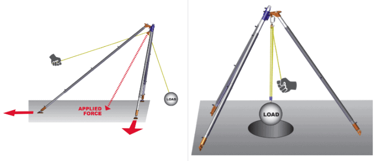
The most dangerous moment in a tripod haul is not the raise itself — it’s the pre-raise configuration where no one checks whether the resultant of haul rope tension and load weight stays inside the tripod’s ground footprint.
The geometry: your load creates a vertical downward force from the tripod head. Your haul rope leaves the head at an angle determined by where your haul team is standing. These two forces combine into a resultant vector. If that resultant points outside the triangle formed by the three tripod leg feet, the tripod rotates about the two closest legs and tips toward the haul team.
With a 5:1 MA, your haul team will be standing well back from the tripod. If they’re outside the leg triangle rather than behind a leg, their haul direction pulls the resultant outside the footprint. Position the haul team so the rope exits through the tripod leg triangle, not around it.
Pre-tension the guy lines before any load goes on
Before loading, tension each guy line using a non-working 3:1 rigged temporarily to each one. This removes slack that would allow initial leg movement when haul load comes on. A leg that shifts even a few inches at load-on moves your resultant vector unpredictably. This step takes three minutes. A tipped tripod takes considerably longer.
04 — Operation
Keep the load inside the tripod
Patient attachment happens inside the tripod — the load should hang directly below the head when viewed from any angle. An offset load introduces diagonal force and bending moment into the head connection. Use a tagline to manage rotation and swing during the raise. At 30 feet of vertical travel, a few degrees of drift creates significant horizontal displacement at the top.
Call the raise in increments
Five-foot increments with a deliberate pause and visual check at each one. Confirm the load is centered, the haul system is running clean, the belay is tracking, and edge protection is still correctly positioned. A 30-foot raise with five checkpoints gives you five opportunities to catch a developing problem.
The surface transition is a separate evolution
When the load clears the opening, the geometry changes completely. The load transitions from vertical to horizontal, introducing lateral loading the system wasn’t designed for. Have a clear plan for this transition before the raise begins — where does the patient go, who manages the handoff, is the belay long enough to stay attached through it. These are questions with answers you need before the haul starts.
Verify all rigging configurations against current NFPA 1006 and manufacturer specifications before operational use.
Peace on your Days
Lance