Beyond “Bombproof”: How System Orientation Redefines Anchor Physics
1. Introduction: The Myth of the Absolute Anchor
In high-stakes technical rigging, the term “bombproof” is often used as a static descriptor—a permanent label assigned to a massive tree or a structural steel beam. However, for the master technician, an anchor is not a static object; it is a context-dependent decision. An anchor’s reliability is inextricably linked to the magnitude, duration, and, most critically, the direction of the force applied to it.
The rigger who assumes that an anchor evaluated for a vertical lower remains “bombproof” for a horizontal highline commits a fundamental error in physics. The transition from a vertical mainline system to a horizontal tensioned system represents a total shift in system dynamics. Moving the resultant force vector from the vertical to the horizontal plane changes the mechanics of the anchor from one of axial compression to one of leverage and displacement. In this environment, “bombproof” is not a rating; it is an orientation-specific conclusion.
2. Point 1: Vector Direction and the Geometry of Force Multiplication
The loading profiles of vertical and horizontal systems are governed by disparate physical interactions with the anchor feature and the environment.
- Vertical Systems: In these configurations, loads align with the gravitational vector. This typically results in downward shear or axial compression. When utilizing a tree as a vertical anchor, the force presses the trunk into the ground. The anchor’s mass and its engagement with the soil are aligned with the force, maximizing stability through compression.
- Horizontal Systems: Forces act primarily in tension, and the geometry of the system introduces Force Multiplication. In systems with wide trackline angles (150°–175°), the resultant force at the anchors can reach several times the actual suspended load.
The physics of a natural anchor, such as a tree, illustrates the danger of this transition. Vertically, the tree is a pillar of compression. Horizontally, it becomes a lever arm. The magnitude of this hazard is dictated by attachment height; a force applied high on the trunk creates a significant bending moment (torque) that exploits the anchor’s weakest resistance modes: uprooting and rotation. To mitigate this in high-tension environments, the Tensionless Hitch is the preferred interface. Unlike standard knots, which induce a 20–40% loss in Minimum Breaking Strength (MBS) due to tight fiber bends, the tensionless hitch relies on friction to preserve nearly 100% of the rope’s MBS, ensuring the anchor connection does not become the system’s weakest link under multiplied forces.
3. Point 2: The Illusion of Equalization—Load-Sharing vs. Load Concentration
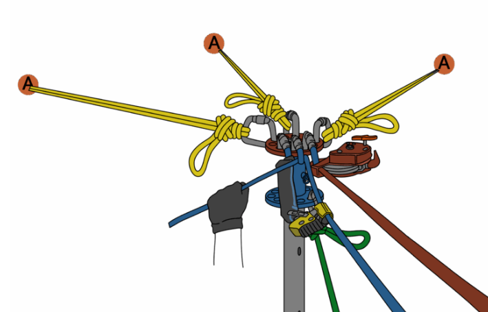
A common cognitive trap is the belief that a “multi-point” anchor naturally shares the load. While gravity assists this process in vertical systems, horizontal applications often introduce Triaxial Loading—multi-plane stresses that can transform “equalized” rigging into single-point failures.
- Vertical Self-Equalization: Gravity assists the system during the “settling phase.” As load is applied, rope stretch and master point movement allow the legs to redistribute forces. Even if geometry is imperfect, the system naturally shifts until all legs engage.
- Horizontal Rigidity: Horizontal systems are pre-tensioned using low-elongation materials to eliminate sag. This pre-tensioning is the critical mechanism that enforces the Non-Extending (NE) principle of ERNEST; it locks the system geometry to prevent the dangerous transition from a static to a dynamic state. However, this rigidity also “locks in” minute differences in leg length. A difference of mere millimeters can cause a single leg to bear the entirety of the multiplied system load.
The technical distinction is governed by pathing. A 90° directional anchor (redirecting a single rope) experiences 141% of the system load because it must resist the combined pull of two active vectors. Conversely, a 90° load-sharing anchor (distributing a single load between two points) results in approximately 71% distribution per leg.
4. Point 3: Redundancy Dynamics and Managing the “Slam Factor”
The ERNEST principles remain the non-negotiable framework for all rigging, but the behavior of redundancy shifts as vectors rotate. In vertical systems, redundancy is about “load capture”—the backup catches the load quickly with minimal extension. In horizontal systems, redundancy must focus on geometry preservation.
Failure in a high-tension horizontal system generates “system extension” (slack), resulting in a catastrophic “slump.” Because these systems store immense energy, the load accelerates during this slump, creating a dynamic shock load that can trigger cascading failures in the remaining hardware.
THE SLAM FACTOR: Lateral Potential Energy Horizontal and offset systems store lateral potential energy by pulling the load away from its natural gravitational fall line. If a deflection component or anchor fails, the system does not fail downward; it releases this energy as a violent pendulum swing toward the terrain or structure. In this scenario, the mainline becomes a pivot point. Because the hazard is lateral rather than vertical, a standard vertical belay is physically incapable of preventing the impact.
5. Summary: Why Geometry is Physics
In complex rigging, function defines force. The technician must look beyond material strength and analyze the stability of the system as a whole.
The Three Final Rules of Anchor Evaluation:
- Context is Absolute: Anchor evaluation must be orientation-specific. Never reuse a vertical evaluation for a horizontal pull; a feature that is immovable when pressed down can be highly vulnerable when pulled sideways.
- Stability Governs Strength: Reliability is defined by resistance to displacement—friction, leverage, and root spread—not just the raw breaking strength of the material.
- Function Defines Force: Distinguish between ropes “fighting gravity” (Tracklines) and those “guiding the load” (Tracking lines). High-tension tracklines multiply forces and require the strictest adherence to redundancy and MBS preservation.
“Bombproof” is not a permanent label; it is a direction-specific conclusion that must be re-validated every time a vector shifts.
Peace on your Days
Lance