Rope Rescue Math – Understanding High-Directional Forces
In rope rescue, knowing the numbers can be the difference between a safe system and one that’s on the edge of failure. When working with high-directionals—such as aerial ladders, tripods, or A-frames—forces don’t just act straight down; they spread out along multiple paths. The diagrams you’ve seen are more than pictures—they are precision tools that combine algebra, geometry, and trigonometry to help rescuers visualize and calculate these forces before committing to a rig.
This guide breaks down how those diagrams work, what the formulas mean, and why angle selection is one of the most important decisions you can make in the field.


Core Principles
Vectors
A vector describes a force with both magnitude (size) and direction. In rope rescue, every load, haul, and anchor force is a vector.
Mechanical Advantage (MA)
This is the multiplier that shows how much your hauling system increases your pulling force. A 3:1 MA theoretically triples your effort—but real-world friction always lowers this number.
Friction
Rope moving over pulleys, carabiners, and edges loses energy to friction. This reduces the effective mechanical advantage and increases the hauling effort.
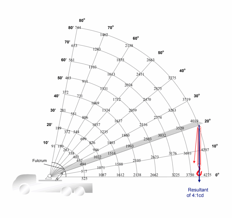
The High-Directional in Action – Vectors at the Tip
At the tip of your high-directional, three key forces create a vector triangle:
-
Load – The vertical force from the weight you’re moving.
-
Haul – The horizontal force from your rope system pulling on the load.
-
Resultant – The total force acting on the tip, created by combining Load and Haul. This is found by vector addition and is often marked on diagrams as an arc value.
Understanding this triangle is critical—it tells you how much stress your equipment, anchors, and structure will endure.
The Math Behind the Diagram
Two main formulas bring the diagram to life:
1. Resultant Force (Vector Sum)
From the Pythagorean theorem:
Formula:R = sqrt(V² + H²)
Where:
-
R = Resultant force
-
V = Vertical (load) force
-
H = Horizontal (haul) force
This gives the total combined force on the high-directional tip.
2. Stress on a Tension Member (Law of Sines)
Formula:Stress = (M × sin(C)) / sin(T)
Where:
-
Stress = Force on the tension member (e.g., back-tie)
-
M = Magnitude of the resultant force (from the diagram)
-
C = Angle of the resultant force
-
T = Angle between the tension member and the high-directional
This calculation ensures your anchors and tension members can handle the actual loads—not just estimated ones.
Why Angles Matter – The Physics of Leverage
The single most important lesson from these diagrams is how angle changes affect force.
-
Low Angles (e.g., 20°) – Force skyrockets. A shallow high-directional acts like a long lever arm from the pivot point, multiplying torque and drastically increasing the resultant force.
-
High Angles (e.g., 80°) – Force is lower. A steeper high-directional shortens the lever arm, reducing torque and the stress on your anchors.
Practical Takeaway
These diagrams are pre-calculated safety references. They allow rescuers to make informed, immediate decisions about equipment choice, anchor placement, and operating limits without having to run calculations under pressure. By pairing visual geometry with tested formulas, you can predict and control forces before you ever load the system.
The end result: a safer, stronger, and more efficient rope rescue operation.
Peace on your Days
Lance