1. Executive Purpose and Scope
In technical rescue, patient packaging is not an accessory task performed “before the rigging starts.” It is the first structural decision in the evacuation system because it determines how the patient will behave as a load once gravity, friction, and motion are introduced. Packaging converts an injured person into a predictable, restrained mass with a controlled center of gravity, stable orientation, and redundant attachment interface. If packaging is weak, every downstream component—friction devices, mechanical advantage, high directionals, anchors, and attendants—must compensate for a load that is no longer mechanically stable.
The scope of this report is the packaging and transport architecture used when a patient must be moved through technical terrain, confined spaces, steep slopes, or vertical environments. It focuses on how packaging integrates with rope systems (mainline and secondary line or Twin Tension Rope Systems), how force travels from the patient into the rigging, and how technicians prevent packaging-driven instability from becoming a system-level hazard.
The packaging objectives are operational requirements and must be verified before committing any load to rope:
- Immobilization: Prevent shifting, rotation, sliding, or progressive loosening that changes the center of gravity during movement.
- Protection: Build a protective interface that reduces abrasion, pressure injury, impact exposure, and environmental contamination.
- Control: Ensure the patient behaves as a managed load—stable under vertical, diagonal, and horizontal movement—without creating unplanned dynamic inputs.
Once these objectives are met, packaging becomes a structural asset rather than an operational liability.
2. System Architecture and Force Path Analysis
Packaging architecture must be analyzed as a load path. The rigger’s job is to ensure force travels cleanly from the patient into the attachment interface, into the litter or stretcher structure, through the bridle, and into the rope system—without creating rotating moments, sliding tendencies, or unintended compression points. This is where “internal vs. external” lashing logic matters: internal lashings stabilize the patient’s mass; external lashings stabilize the patient relative to the frame and protect the assembly.
Force Path Mechanics
Packaging functions as two structural layers with different roles:
- Internal Lashings (Load Stabilization Layer): These secure the patient’s center of mass and prevent migration under gravity. The goal is to prevent the pelvis and torso from shifting as the orientation changes. Internal lashings should be treated as the primary “anti-slip” architecture, not as comfort straps. The pelvis is the foundation: if pelvic control fails, the entire patient migrates, and every other strap becomes reactive.
- External Lashings (Containment and Frame Integration Layer): These bind the patient to the litter/stretcher structure, manage extremities, protect against abrasion, and prevent the assembly from “opening” during drag or lift transitions. External systems (cross-straps, spider straps, containment lashings) are not substitutes for internal stabilization; they complete the architecture by locking the stabilized patient into the frame.
Technical Componentry and Load Interfaces
Patient packaging devices must be described by their load-rated attachment points and their intended vector behavior:
- Yates Spec Pak: A Class III harness/backboard integration designed for vertical or diagonal movement in restricted spaces. The load must be carried through the rated master attachment points, not through non-rated handles or accessory features. The Spec Pak is structurally efficient when the objective is compact profile, predictable vertical lift, and controlled alignment through confined openings.
- Sked Stretcher: A flexible plastic stretcher that “conicalizes” under vertical loading, producing a wedge effect that can improve containment when properly padded and centered. This behavior can be an advantage (increasing stability) or a failure driver (creating pressure points or migration) depending on padding quality, strap routing, and bridle geometry.
Primary Load-Bearing Interfaces
Device: Yates Spec Pak
- Master Attachment Point: Primary lifting ring(s)
- Intended Function: Vertical load transfer with controlled body alignment
Device: Yates Spec Pak
- Master Attachment Point: Chest-level attachment options (where configured)
- Intended Function: Lower-profile lift geometry for confined transitions and reduced “top-heavy” behavior
Device: Sked Stretcher
- Master Attachment Point: Bridle attachment system (centered)
- Intended Function: Vertical lift through a balanced bridle that prevents roll and limits swing
Device: Sked Stretcher
- Master Attachment Point: Horizontal distribution points (where configured)
- Intended Function: Level transport with reduced pitch and reduced patient rotation
Packaging success is demonstrated when the patient remains mechanically quiet: no progressive sliding, no rotation growth, and no strap migration during test-load and initial movement.
3. Geo-Environmental Engineering and Risk Analysis
Terrain and environment determine packaging requirements because they determine load behavior. Packaging that is “adequate” on flat ground can become mechanically invalid when slope, suspension, wind, water, or restricted clearances introduce new force vectors.
Terrain Classification and Packaging-Driven Load Behavior
As terrain transitions from Class 3 to Class 4/5, packaging must be treated as a technical control system rather than a restraint system. The move into Class 4/5 mandates two-rope redundancy and packaging that can tolerate suspension without internal migration.
Key environment-driven risk factors:
- Surface Friction: Loose gravel and scree increase litter slide and roll tendencies, creating frequent shock inputs as the litter catches and releases. Bedrock reduces snag risk but can accelerate travel and increase braking demand; packaging must prevent patient migration under repeated braking pulses.
- Moisture and Contamination: Mud and water increase patient and litter mass and can reduce strap friction consistency. Wet environments also degrade handling precision. Packaging must maintain tension stability under moisture, including strap routing that resists loosening during vibration.
- Wind: Wind introduces lateral vectors that rotate suspended loads. Packaging must prevent “patient roll inside the device,” which becomes a compounding hazard during overhangs and edge transitions.
Physiological Risk Factor
Suspension introduces physiological risk, especially when a patient is held vertically with concentrated strap loading. Vertical suspension time must be minimized, and operational planning must prioritize efficient transitions—especially when patient condition or packaging configuration creates circulation risk. Packaging architecture must therefore support rapid orientation control and stable repositioning rather than trapping the team in prolonged vertical hang time.
Terrain Difficulty Matrix
- Class 1: Minimal packaging complexity; movement control is primarily manual.
- Class 2: Packaging must tolerate bumps and uneven travel; emphasis on containment and pressure protection.
- Class 3: Packaging must resist sliding and rotation under intermittent rope assistance.
- Class 4: Packaging must be engineered for two-rope systems; patient must remain stable under partial suspension and exposure.
- Class 5: Packaging must be fully suspension-ready with redundant attachment logic and strict migration prevention.
The central risk principle is simple: as exposure increases, packaging becomes less forgiving. Any small internal shift becomes a major force-path problem once the load is suspended.
4. Operational Deployment Protocol
Packaging must follow disciplined sequence because sequence determines whether the patient becomes stable early or remains unstable while the team adds complexity around them. The protocol below is designed to prevent “late-stage correction,” where teams attempt to fix migration after the patient is already committed to rope.
Packaging Sequence
Yates Spec Pak Sequence
- Waistband: Establish center-of-mass control and prevent downward migration.
- Leg Straps: Lock lower-body positioning and prevent sliding during vertical lift.
- Shoulder Straps: Secure torso alignment without restricting airway access.
- Head Security: Apply head/forehead controls to prevent cervical traction and uncontrolled head movement.
Sked Stretcher Sequence
- Reverse-roll / staging: Neutralize material memory and prepare predictable wrap behavior.
- Positioning: Center the patient correctly to prevent roll bias and bridle offset.
- Bridle attachment: Attach with centered geometry so lift remains level and roll-resistant.
- Internal integration: Secure internal stabilization before relying on external straps; padding must eliminate voids that create compression collapse and migration.
Maneuvering Tactics for Constrained Environments
Transport tactics are selected based on clearance and floor stability, not preference:
- Turtle Crawl: Low clearance movement under obstacles where bearers support from below.
- Caterpillar Method: Low-overhead corridors requiring staged pass-through movement.
- Static Pass: Hand-to-hand transfer where walking creates unacceptable slip risk; requires stable hand positions and coordinated movement commands.
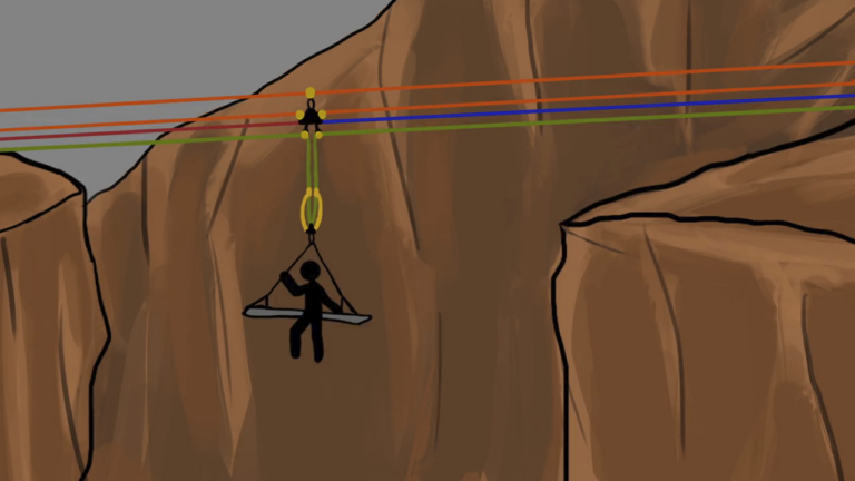
Vertical Tending Protocol
The litter tender is not optional labor; the tender is the control interface that prevents wall strikes, manages overhang transitions, and maintains clearance during lip conversion. The tender must be able to micro-adjust position and control litter attitude. Fine adjustment tools (micro-MA systems) are used to manage position control without introducing uncontrolled slack.
Pre-Movement Verification Checklist
- [ ] Redundancy confirmed: Two-rope architecture verified for Class 4/5 movement.
- [ ] Strap routing confirmed: No strap paths exposed to sharp rails, edges, or abrasion points.
- [ ] Void padding complete: No gaps that allow collapse or progressive migration.
- [ ] Attachment points verified: Load routed through rated attachment interfaces only.
- [ ] Lift check executed: Controlled partial load confirms symmetry, stability, and no patient shift.
Packaging is validated before movement begins, not after the system is committed.
5. Comparative Insights and Device Benchmarking
Device selection is a systems decision. The “best” packaging device is the one that matches the environment, the patient’s condition, and the movement architecture without adding unnecessary complexity or creating new failure modes.
Special Population Adaptations
- Pediatric patients: Packaging must account for head-to-body proportion, rapid heat loss, and the need for aggressive void padding to prevent internal movement.
- Patients with disabilities or prosthetics: Lashings must be adapted to avoid creating pressure injury points, and the system must prevent prosthetic-induced leverage or snag risk.
- Low-responsiveness or medically fragile patients: Packaging must prioritize airway access and stable orientation control; movement must minimize oscillation and abrupt braking pulses.
Device Selection Matrix
Spec Pak
- Operational Context: Confined spaces, shafts, restricted openings
- Primary Advantage: Compact, integrated Class III harness behavior with strong vertical control
Sked Stretcher
- Operational Context: Narrow openings, low-clearance transitions, drag-to-lift conversions
- Primary Advantage: Conforming containment with vertical wedge effect when correctly padded and centered
Basket Litter
- Operational Context: Open terrain, prolonged transport, helicopter interface environments
- Primary Advantage: High lateral protection, strong containment profile, stable long-duration transport behavior
The technician’s responsibility is to match device behavior to mission behavior. A device that performs well in one environment can become mechanically inefficient—or unsafe—in another.
6. System Limitations and Failure Considerations
Packaging and transport systems fail when they exceed their tolerance envelope. The most common failure mechanisms are not dramatic hardware breaks; they are predictable degradations: migration, abrasion, loosening, roll bias, and progressive instability.
Critical System Constraints
- Abrasion and routing failure: Strap routing that contacts rails, edges, or hardware creates rapid degradation. Routing must prevent cutting, melting, and progressive wear.
- Migration under cyclic loading: Repeated brake pulses, bumps, and wall contact can slowly pull the patient out of position unless pelvic control and void padding are correct.
- Environmental control failures: IDLH environments impose additional requirements (air management, extraction speed constraints, and rescue-of-rescuer architecture). Packaging must support rapid movement without rework cycles.
- Human-factor instability: Panic, uncontrolled movement, or poor communication can destabilize the load. The control system must remain procedural: clear commands, predictable tempo, and disciplined stop conditions.
Hard Limits of Vertical Rescue
- Time constraint: Vertical suspension must be minimized and managed intentionally; prolonged vertical hang introduces physiological risk and operational inefficiency.
- Clearance constraint: Packaging and rigging must remain compact enough to negotiate edges and openings without creating swing moments or snag risks.
- Redundancy constraint: Class 4/5 operations require two-rope redundancy; packaging must support that redundancy without creating shared failure points in attachment.
A professional packaging system is proven by stability under stress: test-load stability, movement stability, and transition stability. If the patient remains mechanically quiet, the system remains analytically valid. If the patient becomes an uncontrolled moving mass, the rigging becomes reactive, and risk increases immediately.
Peace on your Days
Lance