A highline is a tensioned rope system used to transport a rescuer and patient across a gap that cannot be crossed any other way — canyons, gorges, building-to-building, or industrial spans. When ground access isn’t an option, a highline is. This chapter covers both system types, the calculations that govern them, and how to operate them under load.
Two System Types — One Decision
Every highline operation begins with a single call: non-reeving or reeving. That decision is made by reading the terrain, not the equipment inventory. Getting it right before the rope comes out determines everything that follows.
Non-Reeving
In a non-reeving system, the load travels along the curve of the tracklines from one side to the other — horizontal movement only. The position of the load in the vertical axis is fixed the moment the system is tensioned. There is no mechanism to raise or lower the load independently during the crossing.
This makes the non-reeving system simpler to build and faster to operate. It works when the terrain cooperates: relatively level anchor points on both sides, adequate clearance beneath the span, and a patient who can be transported horizontally without needing vertical adjustment mid-crossing.
|
Non-reeving is the right call when: anchors are at similar elevations on both sides, clearance beneath the span is confirmed, and the operation requires horizontal transport only. Calculate tension before tensioning. Verify with the load cell. |
Reeving — The English Reeve
A reeving highline adds a dedicated vertical control system — the reeve line — that runs from one anchor side, through the carriage, and back to the other. By managing tension on that line, the team can raise or lower the load independently of the tracklines. The load is no longer fixed at one height. It can be positioned on the Y-axis during the crossing.
That capability comes with a cost. A reeving system is more complex to rig, requires more hardware, more coordination between teams on both sides, and more pre-planning. It is not improvised on scene. The terrain or the patient’s condition makes the decision — if vertical control is needed during the crossing, the system is reeving. If horizontal transport is sufficient, it isn’t.
|
Reeving is the right call when: terrain requires the load to be raised or lowered mid-crossing, access points are at different elevations, or patient packaging demands vertical positioning. Plan it before the operation. Not during. |
The Math Is Not Optional
Before any line goes into tension, someone on the team runs the calculation. Not approximately — actually. The formula governs the relationship between span geometry, load, and the forces entering the anchor system. It is the foundation of every tensioning decision.
|
T = DL / 4Y Required tension (kN) = Distance (m) × Load (kN) ÷ (4 × Available height (m)) |
What Each Variable Means Operationally
|
T — Required tension |
The minimum tension needed in each trackline to maintain the load at the intended height. This is what you’re building to. Verified by the load cell. |
|
D — Span distance |
The horizontal distance between anchors in metres. Longer spans require proportionally more tension. |
|
L — Load |
The combined weight of the rescuer, patient, and equipment in kN. Built from real inputs — not estimated. 1 kN ≈ 102 kg. |
|
Y — Available height |
Usable clearance beneath the carriage after subtracting the load package depth. Not theoretical height — working height. The load package consumes part of it. |
The Variable That Catches People
Y is in the denominator. As Y approaches zero — as clearance disappears — tension approaches infinity. This is not a linear relationship. Halving Y doubles the required tension. Reducing Y by 75% quadruples it. Small reductions in available height create disproportionately large increases in required tension, and every increase in tension goes directly into the anchors and hardware.
|
Available height is not the height above the gorge floor. It is that height minus the vertical space consumed by the load package, rescuer, patient, and equipment hanging below the carriage. Account for it before tensioning. |
A Worked Example
Wilderness canyon rescue. 40 m span. Rescuer 85 kg, patient 80 kg, equipment 20 kg — combined load 1.81 kN. Total available height 7 m. Load package depth 2 m. Usable Y = 5 m.
|
T = (40 × 1.81) / (4 × 5) = 72.4 / 20 = 3.62 kN per trackline Two tracklines independently tensioned to 3.62 kN each, verified by load cell. |
That is the system. Not estimated — measured. The load cell is inline from the start, and the team lead calls the tension value before anyone hauls. Get this wrong and the system either sags the patient into the terrain mid-crossing or drives anchor forces beyond what the rigging was built to handle. Both outcomes are avoidable.
Determining Trackline Count
Once the required tension is known, divide it by the working load limit of the trackline. If the WLL is 20 kN, the working load at a 10:1 safety factor is 2 kN per line. At 3.62 kN required, two tracklines give a combined working capacity of 4 kN — an adequate margin. One trackline does not.
Two tracklines is the practical minimum for a working rescue highline regardless of the calculation. The system is not just carrying a calculated load — it is carrying uncertainty, movement, and real-world variation. Two lines distribute force, improve stability, and provide a genuine working margin.
|
10:1 safety factor is the life-safety standard for technical rescue rope systems. If your calculated tension is 3.62 kN per trackline, your trackline needs a minimum breaking strength of 36.2 kN. The calculator below applies this standard explicitly. |
The 30° Threshold
The formula T = DL/4Y is derived from the geometry of a point load at mid-span and uses a small-angle approximation. When the mid-span angle of the tracklines exceeds 30° from horizontal, that approximation begins to lose accuracy. The formula still provides a useful planning estimate, but results should be treated conservatively, and direct measurement via load cell becomes more critical.
In practice, most rescue highlines operate between 10° and 20°. Angles below 10° indicate very low tension and generous clearance. Angles above 20° indicate elevated tension and should be confirmed against system capacity before the patient loads.
Interactive Tension Calculator
The calculator below applies T = DL/4Y to your specific scenario. Build the load from real weights — rescuer, patient, equipment — and input your span geometry. The tool outputs required tension per trackline, minimum trackline count, and system safety factor against the 10:1 life-safety standard. The animated span visualization shows the V-geometry of the loaded tracklines, with dimension callouts appearing at mid-span — the design condition the formula assumes.
|
[ INTERACTIVE CALCULATOR ] Insert iframe embed of the Highline Tension Calculator here. The calculator allows real-time input of span distance, load (built from rescuer + patient + equipment weights), available height, load package depth, and trackline WLL. It outputs required tension per line, minimum trackline count, system safety factor, and a live animated span visualization with gorge terrain. |
Building the System — Roles and Discipline
The Anchor
The anchor is where discipline either exists or it doesn’t. Every line gets its own independent connection — tracklines, taglines, reeve lines if present. Nothing shared. Each line leaves the anchor in the correct orientation for the direction it is working. The team lead walks both anchors before the system is tensioned.
If a line is misrouted, misoriented, or sharing hardware it shouldn’t share, that gets corrected before the load goes on. In a constrained industrial setting — rooftop to rooftop, structural steel, limited anchor options — creative rigging is sometimes required. The principle doesn’t change. Whatever the anchor looks like, each line still needs its own independent load path.
|
A rigging plate shared between a trackline and a tagline is not independent anchoring. It is a single point of failure dressed up as two. |
Multiple Tracklines — Independent Tensioning
Running multiple tracklines gives the system something a single line cannot: a distributed load and the ability to manage span geometry through differential tensioning. Each trackline has its own independent anchor connection and its own progress capture device. They are tensioned individually to the calculated value, verified by the load cell.
The tracklines define the geometry of the span — the sag, the clearance beneath the load, and the forces going into the anchors. Get the tension right and the system behaves predictably. Get it wrong and you are either chasing clearance mid-operation or driving anchor forces higher than the system was built to handle.
Independent Anchoring Across All Line Types
The same principle that applies to tracklines applies to every line in the system. Taglines, reeve lines, and tracklines each get their own independent anchor connection. None of them share a load path with another.
Each line type carries force in a different direction at a different time. Combining any two into a shared anchor means that a problem with one can immediately affect the other. In a loaded highline, that is not a place for surprises.
Orientation matters as much as independence. Each line needs to leave the anchor in the direction it is actually working. A trackline that is offset or angled at the anchor introduces side-loading into the hardware and friction into the system that shouldn’t be there.
The Carriage
The carriage is organized before the patient loads. Whether that is a Kootenay or another configuration, the team lead confirms what is connected where and what role each connection is serving. Taglines to the correct points. Reeve lines through the correct path. Load connection verified. A cluttered carriage at this stage becomes an unreadable carriage under load, and an unreadable carriage under load is a system the team cannot manage.
Operating Under Load
Non-Reeving — Tension Is the Only Control
Once the patient is loaded on a non-reeving system, the team has one mode of control: tension. The tagline teams move the package by coordinating input — one side applies tension while the other releases simultaneously. The team lead calls the movement. Neither tagline team acts unilaterally.
|
Traverse |
The control side tagline applies tension, fixed side releases simultaneously. Smooth, coordinated, called by the team lead. |
|
Lowering |
Tagline tension reduced on both sides simultaneously. Trackline tension is reduced on the control side. The geometry of the span changes — the sag deepens, and the load descends. Petzl ID on the fixed side controls descent rate. |
|
Raising |
Trackline tension increased on the control side to reduce sag. Tagline tension increased to maintain lateral control. Not linear — small height gains cost disproportionately large tension increases. |
|
Final approach |
As the carriage approaches the fixed anchor, the pace slows and control becomes more deliberate. The ID operator on the fixed side is watching the package arrive and is ready to manage the final lowering. |
Reeving — Two Independent Axes
On a reeving system, the team has two independent axes to manage simultaneously. The control side team manages the reeve — raising, lowering, and holding position. The tagline teams on both sides manage to traverse. The team lead is the communication hub. Any vertical movement gets called before it happens. Any traverse gets called before it happens.
|
X axis — taglines position and traverse the carriage horizontally. Y axis — reeve lines raise and lower the load vertically. Neither axis affects the other. This independence is what makes the reeving system the right tool when terrain demands control in both directions. |
On a sloping reeving system, coordination becomes non-negotiable. The system is pre-loaded by gravity toward the low side and responds immediately to any change in restraint. There is no neutral state. Both high-side tagline operators hold continuously, not resting between moves. When the trackline angle exceeds approximately 45 degrees, two taglines are required on the high side: one for control, one as backup. One tag fails on a loaded slope, and the carriage moves fast.
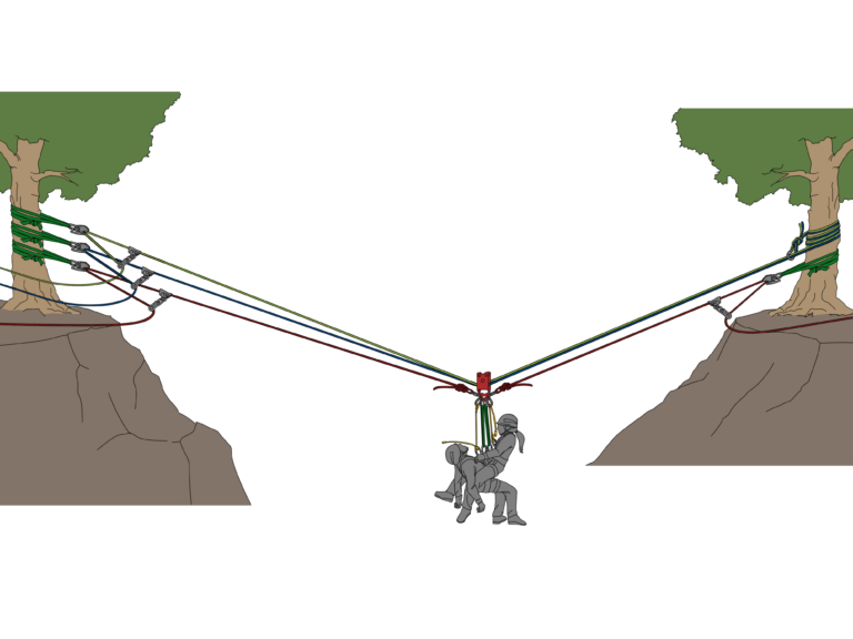
Rescuer and Patient Connection
The connection system for both the rescuer and patient is built around a two-point attachment for each. Two points lock orientation, distribute load across the harness, and ensure a load path remains if any single connection is compromised.
|
Green slings |
Primary structural connection from the carriage to the rescuer. Two points — prevents rotation, maintains upright working position. |
|
Yellow adjustable lanyards |
Secondary attachment for both rescuer and patient. Allows fine position adjustment. Patient’s lanyard connects them independently into the load cluster — they are not riding solely off the rescuer. |
|
Red taglines |
Alpine butterfly knots connect taglines to the carriage. The butterfly is not just a connection — it is also a backup attachment that holds securely under load from any direction. |
A patient in distress is not a stable load. They shift, react, and may be unresponsive deadweight. Two-point attachment for the patient controls that movement — keeps them aligned under the rescuer, prevents rotation, and maintains the load path if any single connection is compromised.
Backup Is Part of the System — Not an Afterthought
In either configuration, the vertical load path has a backup. The team lead makes that call during planning, not during rigging. Backing up a reeving system mid-build because someone remembered it at the last minute is how backup systems get rigged incorrectly under time pressure.
Non-Reeving Backup
The Petzl ID on the fixed side serves as both a progress capture and controlled lowering device simultaneously. It holds the load package at the position during traverse, preventing uncontrolled movement toward the delivery side. When the team is ready to lower, the same device controls descent — feeding rope at a deliberate, stoppable rate. On a system where the geometry is fixed and there is no independent vertical control in the span, this precision at the delivery anchor is what keeps the final phase of the operation clean.
Reeving Backup — Three Configurations
There is no single correct way to back up a reeve system. Three configurations, each with a different trade-off:
Twin reeve lines run in parallel, both independently anchored, both sharing the load actively. The most robust configuration — if one line fails, the other is already carrying the load. Requires the most hardware.
Dual fall arrest, single reeve line with two independent fall arrest devices tracking it passively. Under normal operation, they do nothing. If the primary fails or the load moves uncontrolled, both devices engage. Two devices because a single device can fail to engage — two makes engagement near certain.
Independent backup + ASAP Single reeve line with an independent backup line running alongside it, unloaded. An ASAP tracks the backup line. If the primary fails the backup loads, and the ASAP engages at the carriage level. The backup shares no hardware, no anchor, and no load path with the primary — a failure that takes out the primary cannot simultaneously take out the backup.
|
All three are legitimate. The choice depends on terrain, patient condition, available equipment, and team experience. What is non-negotiable: the vertical load path has a backup, it is in the plan before the operation starts, and it is verified during the anchor walk. |
Stretcher Configuration
When the patient requires a stretcher, the rigging plate below the reeve organizes all connections. Each element has its own hole, its own direction of pull, and its own function. Nothing is stacked or shared.
|
Red slings |
Outermost left holes — one leg of the stretcher bridle. Wide bridle angle keeps the stretcher stable beneath the plate. |
|
Blue slings |
Outermost right holes — other leg of the stretcher bridle. Symmetric load distribution. |
|
Purple sling |
Patient’s independent connection to the plate. Two points of attachment into the system, separate from the stretcher structure — prevent rotation, maintain alignment. |
|
Orange sling + yellow lanyard |
Attendant’s two independent connection points. Separate from both the bridle and the patient connection — allows the attendant to work without loading or disturbing primary connections. |
|
Swivel above the plate |
Not optional. Packages rotate under load — especially stretcher loads where weight distribution shifts. The swivel absorbs rotation before it reaches the reeve system. |
Field Application — How It Comes Together
Everything in this chapter exists to solve one problem: getting a patient across a gap that cannot be crossed any other way. The systems, the hardware, the calculations — none of it matters in isolation. What matters is whether the team can read the environment, select the right configuration, build it correctly, and operate it under pressure with a patient on the line.
The Decision Starts Before the Rope Comes Out
Non-reeving or reeving — that decision is made by looking at the terrain, not the equipment inventory. In a wilderness canyon rescue with anchors at similar elevations and adequate clearance, the non-reeving system is simpler, faster, and entirely appropriate. In an urban shaft rescue or a gorge where the patient needs to be lifted clear of terrain mid-span, the non-reeving system cannot do the job — the geometry is fixed once tensioned. That is a reeving system. Pre-planned, more hardware, more coordination. The team lead needs to have made that call before the system goes up, not after the patient is loaded.
The Team Lead Is Reading the System Throughout
Once the system is operating, the team lead is not pulling rope or managing a tagline. They are reading the system.
• Load cell values against the planned tension
• Carriage position and movement rate
• Patient condition and rescuer communication
• Tagline coordination between sides
• Any change in system geometry — load dropping lower than expected, carriage drifting, a tagline losing tension unexpectedly
Every observation maps back to something calculable. A load dropping lower than expected mid-span means the system is under-tensioned — go back to the calculation. A carriage drifting is a tagline coordination problem. A line losing tension unexpectedly is an anchor or hardware issue that stops the operation until it is identified.
|
The systems work when they are built correctly and operated with discipline. The calculation is not a formality — it is the foundation. The anchor walk is not a checklist exercise — it is the last opportunity to correct a mistake before the patient loads. |
This content is part of a technical rescue training series. The interactive calculator above applies the T = DL/4Y formula to real field inputs and should be used as a pre-operation planning tool in conjunction with formal training, system verification, and direct load cell measurement during tensioning. It does not substitute for competency in technical rescue systems.
Peace on your Days
Lance