Geometric and Mechanical Force Vectors in Complex Rescue Rigging Systems
Executive Summary
In technical rope rescue, anchor systems function as engineered structures rather than ad-hoc attachment points. Their performance is governed by geometric force vectors, mechanical leverage, material capacity, and environmental degradation. This report establishes a disciplined engineering framework for evaluating anchor integrity, analyzing force amplification through geometry, managing mechanical dynamics such as torque and triaxial loading, and selecting appropriate structural and hardware solutions. When properly integrated, these principles produce predictable, resilient systems capable of sustaining life-safety loads under complex rescue conditions.
1. Foundational Framework for Anchor System Integrity
Anchor systems represent the structural foundation of all rope rescue operations. Any weakness at this level propagates downstream, compromising mechanical advantage systems, transport paths, and patient safety. As such, anchor design and evaluation must follow engineering logic rather than equipment familiarity alone.
1.1 Anchor System Hierarchy
| Term | Technical Definition | Operational Role |
|---|---|---|
| Anchor Point | The parent material or substrate (e.g., steel beam, concrete column, live tree). | Governs ultimate system integrity. |
| Anchor | The hardware interface attached to the anchor point (slings, bolts, connectors). | Primary load interface. |
| Anchor System | A redundant, engineered configuration of anchors and rope. | Distributes and controls applied forces. |
1.2 ERNEST as a Performance Standard
ERNEST is applied as a design constraint framework, not a mnemonic:
-
Equalized: Load sharing must be deliberate and predictable. Pre-equalized or focused systems are favored over migrating configurations.
-
Redundant: The system must assume component failure without catastrophic collapse.
-
Non-Extending: Geometry must prevent extension or lurch that would introduce shock loading.
-
Solid: Parent material and hardware must equal or exceed the weakest downstream system element.
-
Timely: Solutions must be simple, correct, and deployable without unnecessary complexity.
This framework establishes anchors as structural systems subject to explicit design limits.
2. Geometric Stress Analysis
Vector Forces and Critical Angle Thresholds
Anchor geometry directly governs internal force amplification. As internal angles increase, leg tension rises non-linearly relative to the applied load.
2.1 Two-Leg Anchor Force Distribution
| Internal Angle | Approximate Load per Leg |
|---|---|
| 0° | 50% (baseline) |
| 60° | ~58% (preferred working range) |
| 90° | ~71% (upper practical limit) |
| 120° | 100% (critical threshold) |
At 120°, each anchor leg carries the full applied load. A 200 kg rescue package results in ~200 kg of force on each anchor, effectively doubling hardware demand. Beyond this angle, force escalation becomes rapid and structurally unsustainable.
2.2 Anchor System Typologies
-
Load-Sharing Anchor Systems (LSA)
Fixed-length, focused systems that are non-extending and failure-tolerant. These are the default for life-safety applications. -
Load-Distributing Anchor Systems (LDA)
Self-equalizing systems (e.g., sliding configurations) that allow master-point migration but introduce extension and shock-load risk during point failure.
From an engineering perspective, LSAs are preferred. LDAs require explicit justification and additional controls.
3. Mechanical Dynamics
Leverage, Bending Moments, and Triaxial Loading
Anchors are rarely subjected to pure axial tension. Real-world conditions introduce torque, leverage, and multi-axis loading that must be anticipated.
3.1 Leverage and Bending Moments
Forces applied away from an anchor’s structural base generate rotational torque. This can:
-
Snap tree limbs,
-
Deform structural steel,
-
Pry mechanical anchors from concrete.
Mitigation Principles:
-
Rig attachments as close to the structural base as possible.
-
Avoid eccentric loading that displaces the force line from the anchor’s intended axis.
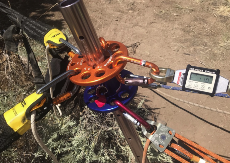
3.2 Triaxial Force Environments
Complex rescue systems often impose simultaneous forces along three axes:
-
X-axis: Horizontal offsets and redirects.
-
Y-axis: Vertical suspended load.
-
Z-axis: Oblique or lateral forces from redirects, wind, or high-directional devices.
Systems involving monopods, gin poles, or A-frames must be evaluated for combined vector resultants. Adequate guying, opposition anchors, and controlled geometry are essential to remain within device and substrate capacity.
4. Structural Transition
From Single-Point to Multi-Point Architectures
Operational competence includes recognizing when a single anchor—regardless of apparent strength—is insufficient. Triggers include marginal substrate quality, poor alignment with load direction, or anticipated vector shifts.
4.1 Multi-Point Strategies
-
Slack Anchor Systems:
A primary anchor carries the full load while secondary anchors remain slack as backups. -
Tensioned Anchor Systems:
Multiple marginal points are pre-tensioned to form a collective master point. -
Back-Ties and Front-Ties:
Back-ties prevent forward translation; front-ties (opposition anchors) stabilize focal points under load.
4.2 Pre-Tensioning Methods
Slack removal and system stabilization are achieved using friction-based techniques or non-working mechanical advantage systems (e.g., compact 3:1 configurations). Pre-tensioning reduces system settling and limits dynamic loading during initial force application.
5. Engineering Solutions
Hardware and Bolt-In Anchor Systems
Where natural anchors are unavailable, engineered hardware solutions are employed.
5.1 Structural Steel Anchors
I-beam clamps and trolleys provide rated attachment points when:
-
Properly seated and aligned,
-
Loaded within their design envelope,
-
Free of eccentric or torsional loading.
5.2 Concrete and Rock Anchors
Applicable substrates must meet minimum compressive strength (≈3,000 PSI). Common anchor types include wedge, sleeve, and drop-in anchors, each selected based on load direction, permanence, and substrate condition.
For temporary life-safety applications, removable bolt systems may be used when installed to specification.
Critical Installation Requirements:
-
Correct drill bit diameter and cutting geometry.
-
Perpendicular drilling and adequate embedment depth.
-
Complete dust removal from the hole.
-
Visual confirmation of proper expansion and seating.
5.3 System Capacity Considerations
System ratings such as Wrap-3 Pull-2 or basket configurations are used as design references, subject to manufacturer specifications, material condition, and inspection protocols.
6. Environmental and Operational Risk Mitigation
Engineering calculations are subordinate to environmental realities. Heat, abrasion, and load cycling can rapidly degrade system capacity.
6.1 Thermal Exposure
Synthetic fibers begin to soften near 82°C (180°F), with potential strength losses approaching 40% under sustained exposure. Thermal damage may not be visually detectable.
Controls:
-
Heat shielding and insulation,
-
Strategic rerouting,
-
Use of heat-resistant components where required.
6.2 Abrasion and Cyclic Loading
Repeated movement over edges accelerates fiber fatigue beyond simple bend-radius effects.
Mitigation Measures:
-
Edge protection (pads, rollers),
-
Elevated redirection using A-frames or AHDs,
-
Minimization of unnecessary movement under load.
7. Engineering Verification Checklist
Before committing a system to load:
-
Equalized: Are internal angles controlled and loads shared predictably?
-
Redundant: Is single-point failure prevented?
-
Non-Extending: Will loss of any element avoid dynamic extension?
-
Solid: Are all components verified against the weakest system link?
-
Timely: Is the solution simple, correct, and appropriate?
-
Environmental: Are heat, abrasion, and cycling hazards addressed?
Conclusion
Effective rescue anchor systems are the product of disciplined geometry, mechanical understanding, material verification, and environmental control. When anchors are treated as engineered structures rather than improvised attachments, system behavior becomes predictable, resilient, and aligned with the demands of modern technical rescue operations.