This document serves as a field reference guide for trained rescue professionals. Its purpose is to consolidate the critical principles of anchor selection, knot application, and load dynamics to ensure operational safety and efficiency in technical rescue scenarios. The information contained herein is derived from established rescue standards and practices and is intended to supplement, not replace, comprehensive training and field experience.
In technical rescue, there is no room for ambiguity. A rigorous understanding of anchor strength and system redundancy is not merely best practice; it is the bedrock of every safe operation. Every decision, from selecting a tree to rigging a multi-point system, must be guided by a clear knowledge of the forces involved and the capacity of the components to handle them. The principles outlined below form the essential framework for constructing reliable and resilient rescue systems.
Let Us Jump In!
The primary operational standard in technical rescue is the creation of two independent anchors. Each of these anchors must have a focal point capable of supporting a load of 20+ kilonewtons (kN). The strategic importance of this standard cannot be overstated. It allows a rescue team to separate their two primary systems (e.g., a main line and a belay line). This separation ensures that a catastrophic failure in one system does not compromise the other, which remains fully capable of supporting the entire rescue load.
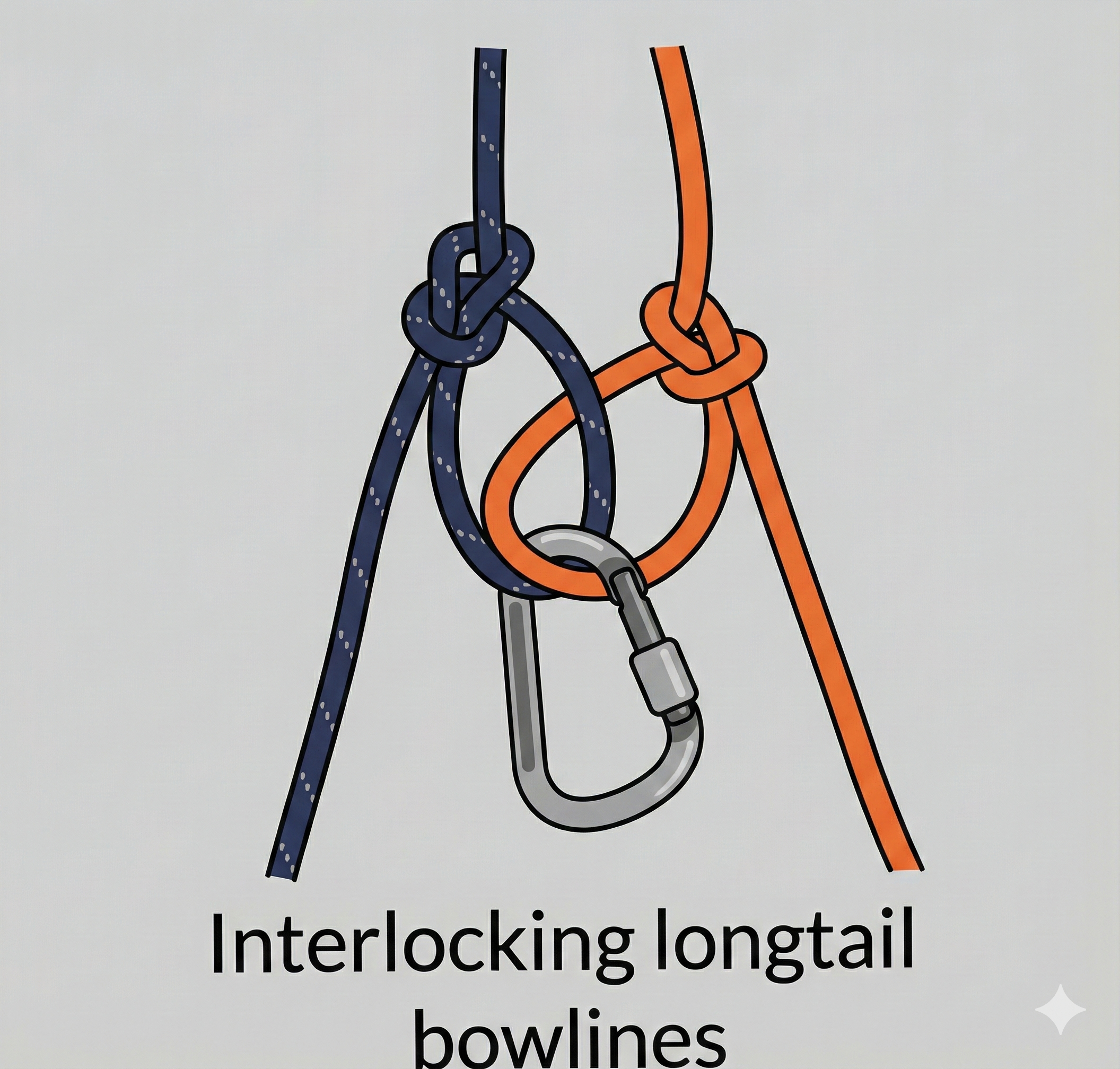
Interlocking Longtail Bowlines
-
What: Two ropes (blue and orange) are connected by interlocking their longtail bowline knots. A carabiner is clipped through the loop of the blue rope’s bowline.
-
How: A bowline with a long tail is tied in the end of each rope. The loops of the bowlines are passed through each other, creating an interlocking connection.
-
Why: This is a method for connecting two ropes together for applications like rappelling or lowering, where a redundant connection is desired. The interlocking bowlines provide a secure join, and the long tails can be used for additional purposes or security. The carabiner is likely a point of attachment for a load or a belay device.
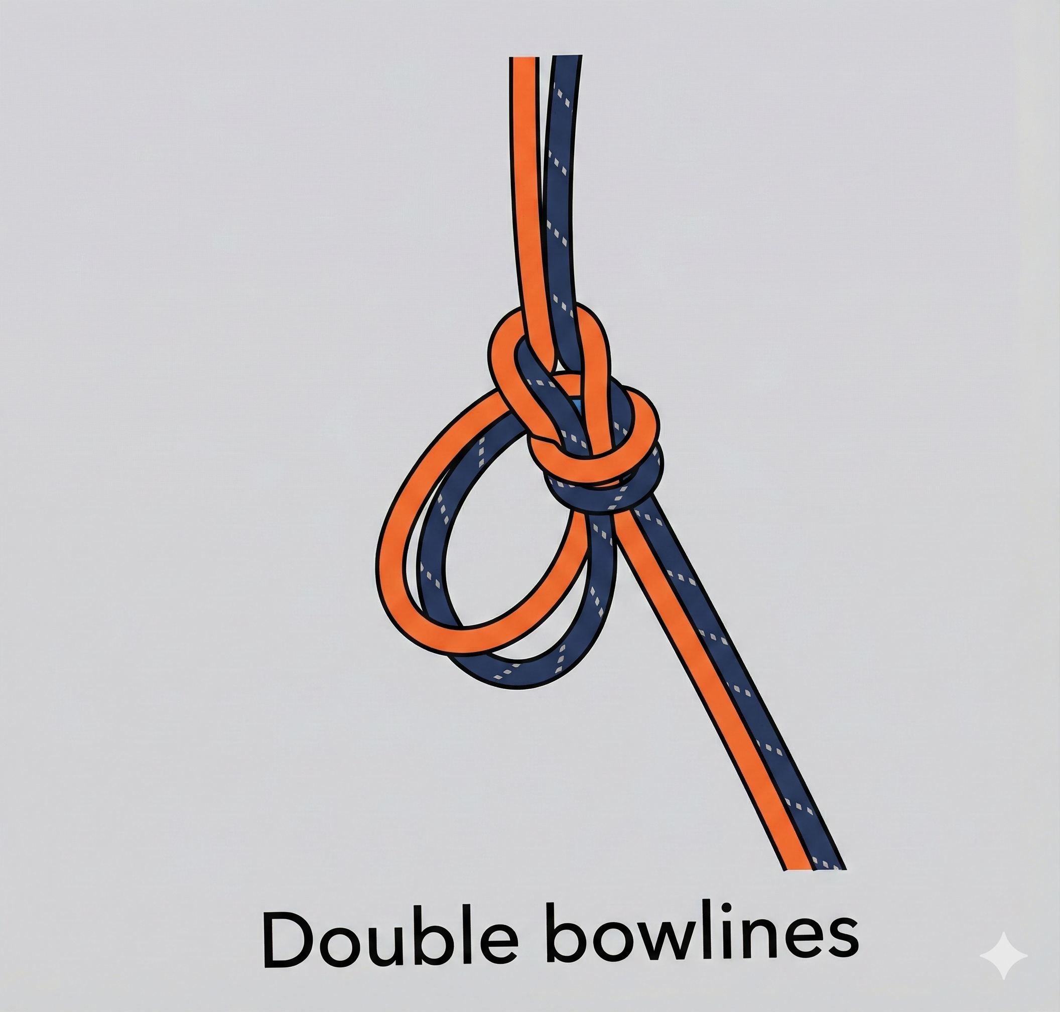
Double Bowlines
-
What: Two ropes (blue and orange) are connected using a double bowline knot.
-
How: A double bowline, also known as a bowline on a bight, is tied using both ropes simultaneously. This creates two loops, one from each rope, that are part of the same knot structure.
-
Why: The double bowline provides a secure, non-slip loop that can be used for anchoring or connecting ropes. When tied with two ropes, it creates a redundant loop, meaning that if one rope fails, the other is still part of a complete knot.
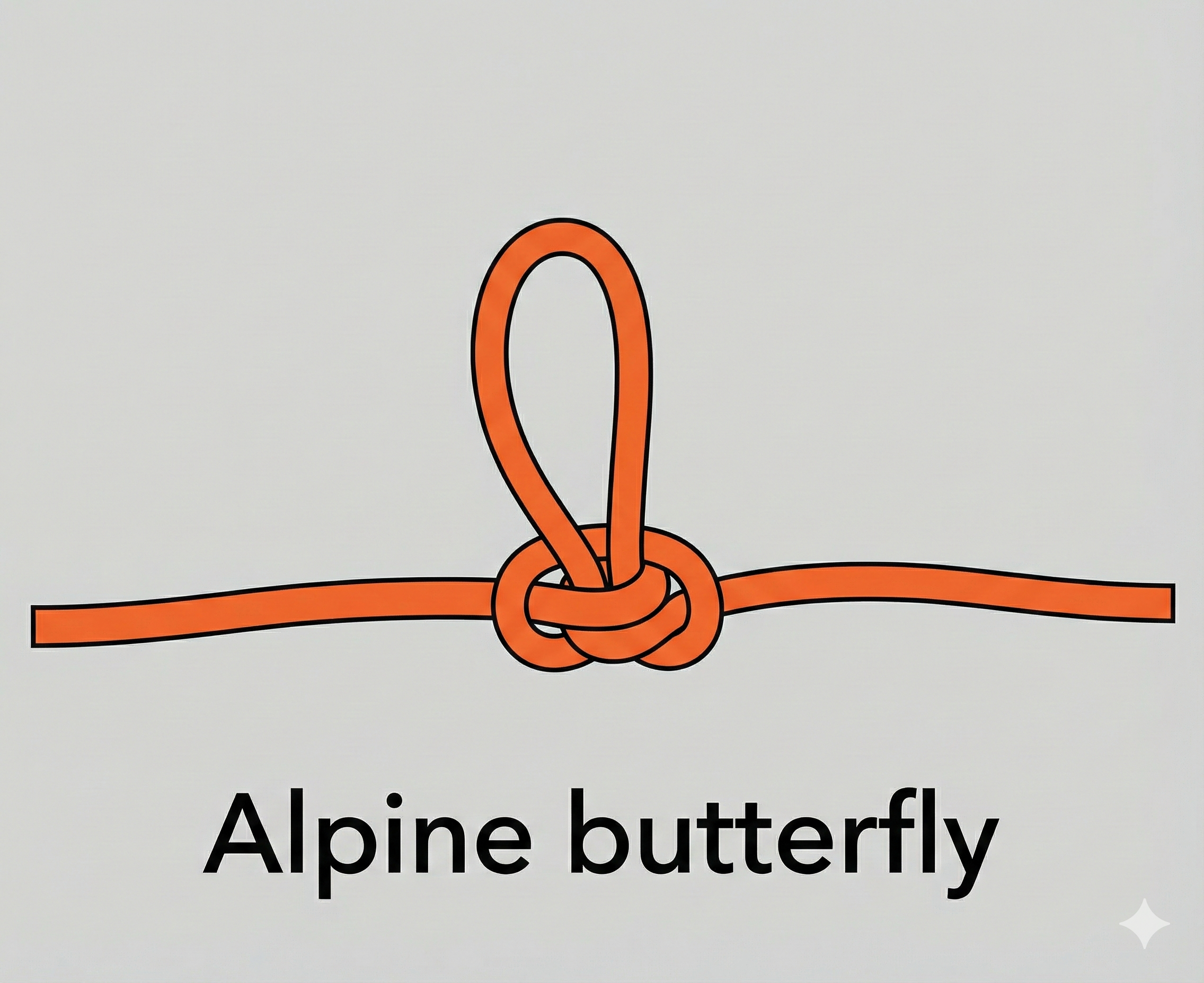
Alpine Butterfly
-
What: A single orange rope has an alpine butterfly knot tied in the middle of it.
-
How: The knot is tied in the “middle” of the rope, meaning it’s not at an end. It creates a fixed loop that can be loaded from either direction of the rope or the loop itself without the knot slipping.
-
Why: The alpine butterfly is a versatile knot used to create a secure loop in the middle of a rope. It’s commonly used in climbing and rescue for clipping into a multi-person rope team, isolating a damaged section of rope, or creating a mid-line anchor point.
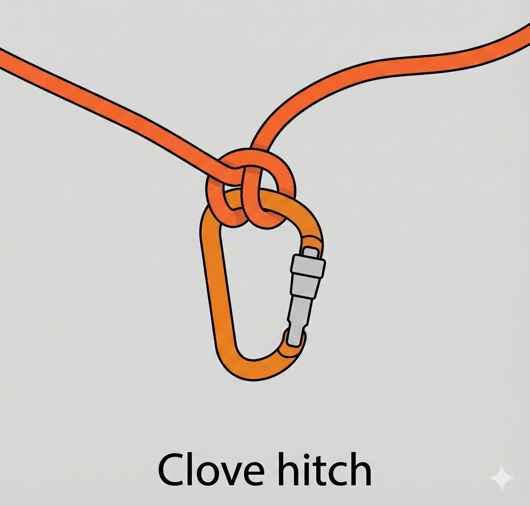
Clove Hitch
-
What: An orange rope is secured to a carabiner using a clove hitch knot.
-
How: The clove hitch is tied around the spine of the carabiner. It consists of two half-hitches in opposite directions, which creates a knot that is easy to adjust.
-
Why: The clove hitch is a very common knot in climbing and rigging because it’s quick to tie and, most importantly, easy to adjust the length of the rope on either side of the knot without untying it. It’s often used for securing a climber to an anchor or for general rigging purposes where adjustability is needed.
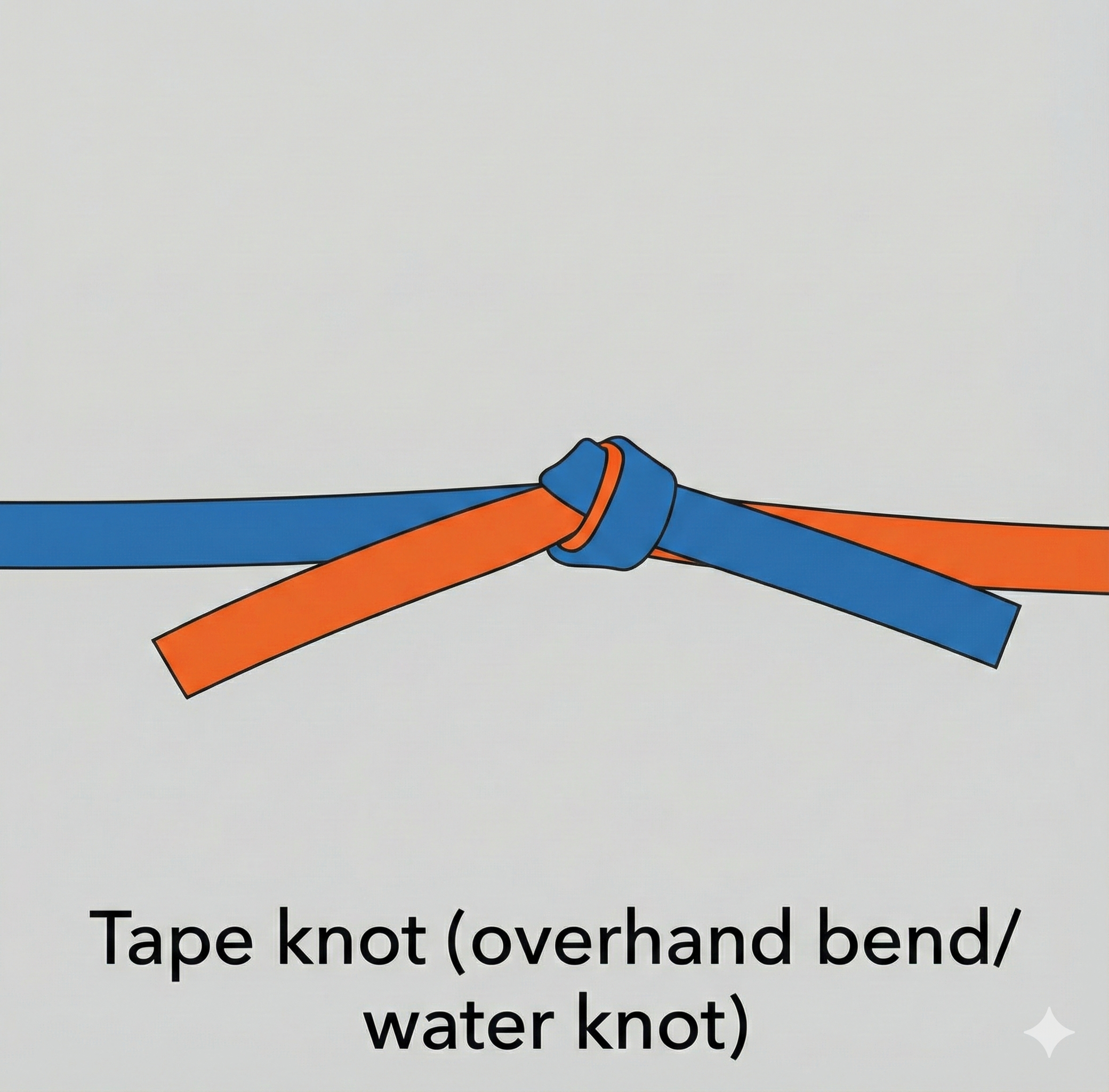
Tape Knot (Overhand Bend / Water Knot)
-
What: A connection between a blue flat webbing strap and an orange flat webbing strap.
-
How: An overhand knot is loosely tied in one end of the webbing. The other end is then fed into the knot from the opposite direction, tracing the path of the original knot perfectly so that the two straps lie flat against each other (“follow-through” method).
-
Why: This is the standard knot for joining flat materials like tubular webbing. Because webbing is flat, standard rope knots often slip or deform; the water knot maximizes surface area contact to prevent slippage. It is commonly used to create slings or “runners” for anchors.
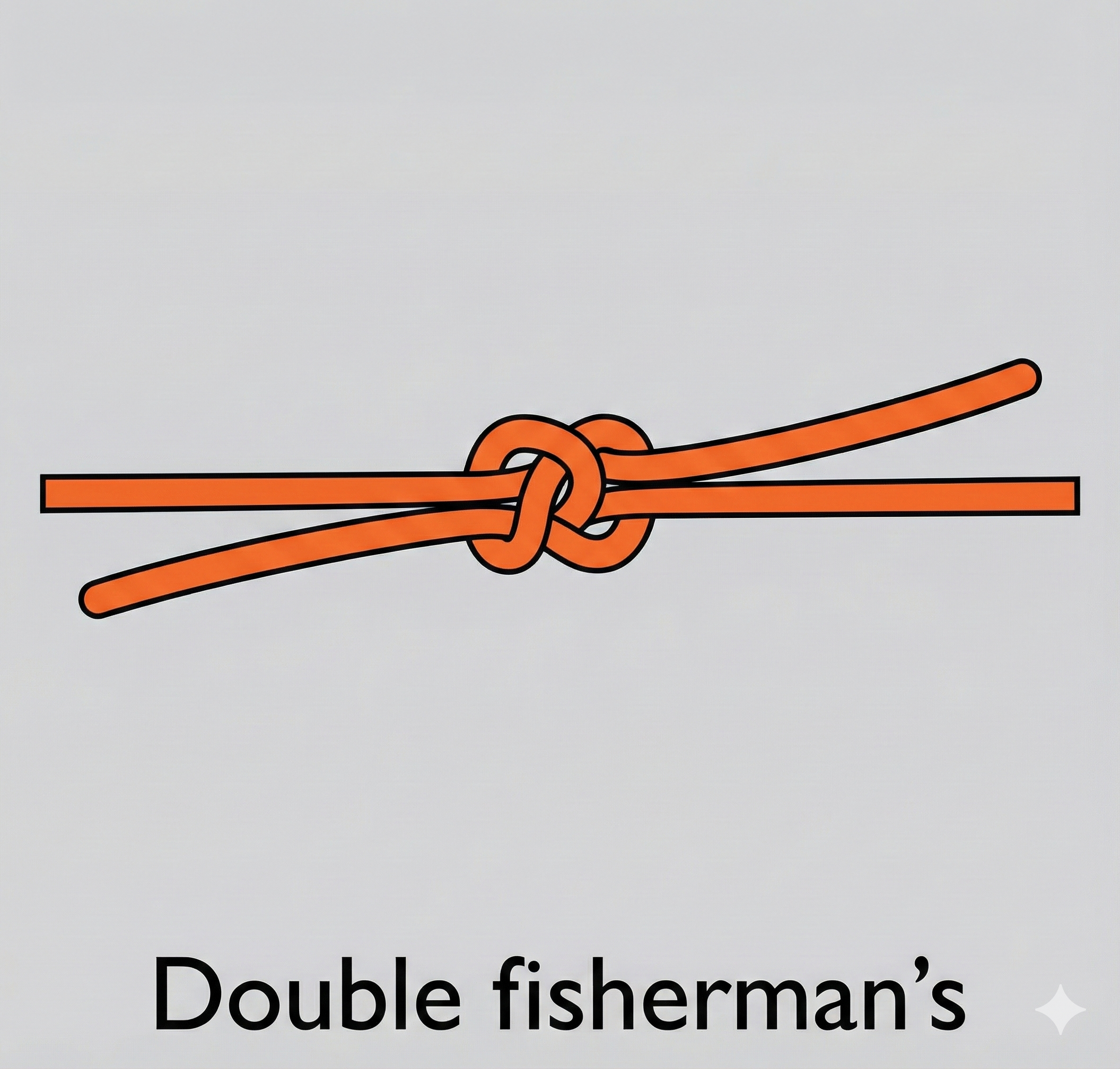
Double Fisherman’s Knot
-
What: Two orange rope ends are joined together by two compact, barrel-shaped knots that press against each other.
-
How: A double overhand knot (strangle knot) is tied with one rope end around the standing part of the other rope. The same is done with the second rope end around the first. When the standing parts are pulled, the two knots slide together and lock.
-
Why: This is an extremely secure way to join two ropes (especially of similar diameter) or to create a closed loop of cord (like a Prusik loop). It is favored because it is very difficult for it to shake loose, though it can be very hard to untie after it has been heavily loaded.
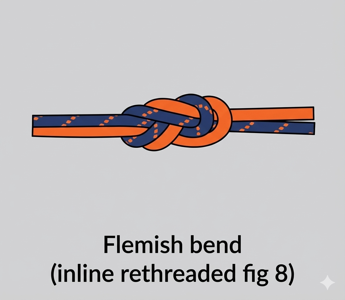
Flemish Bend (Inline Rethreaded Figure 8)
-
What: An orange rope and a blue rope are joined together using a figure-eight structure.
-
How: A standard figure-eight knot is tied in the end of one rope. The end of the second rope is then threaded backwards through the first knot, following the exact path of the first rope’s strand, entering where the first rope exits and exiting where the first rope enters.
-
Why: This is a very strong and secure bend used to join two climbing or rigging ropes (e.g., for a long rappel). It is preferred over other bends because it is relatively easy to untie after loading and is easy to visually inspect for correctness.
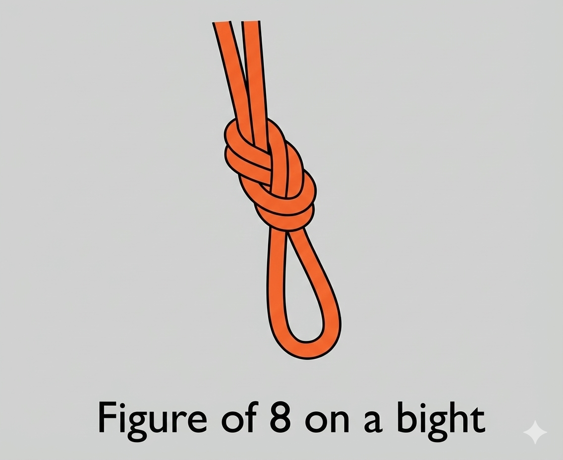
Figure of 8 on a Bight
-
What: A single orange rope formed into a fixed loop at the end.
-
How: A bight (a folded section of rope) is treated as a single strand and used to tie a figure-eight knot. This creates a loop that does not slide or close under load.
-
Why: This is the “gold standard” loop knot for life safety applications (like tying into a harness or creating an anchor point). It is strong, maintains a high percentage of the rope’s original strength, and is unlikely to slip or jam so tightly that it cannot be untied.
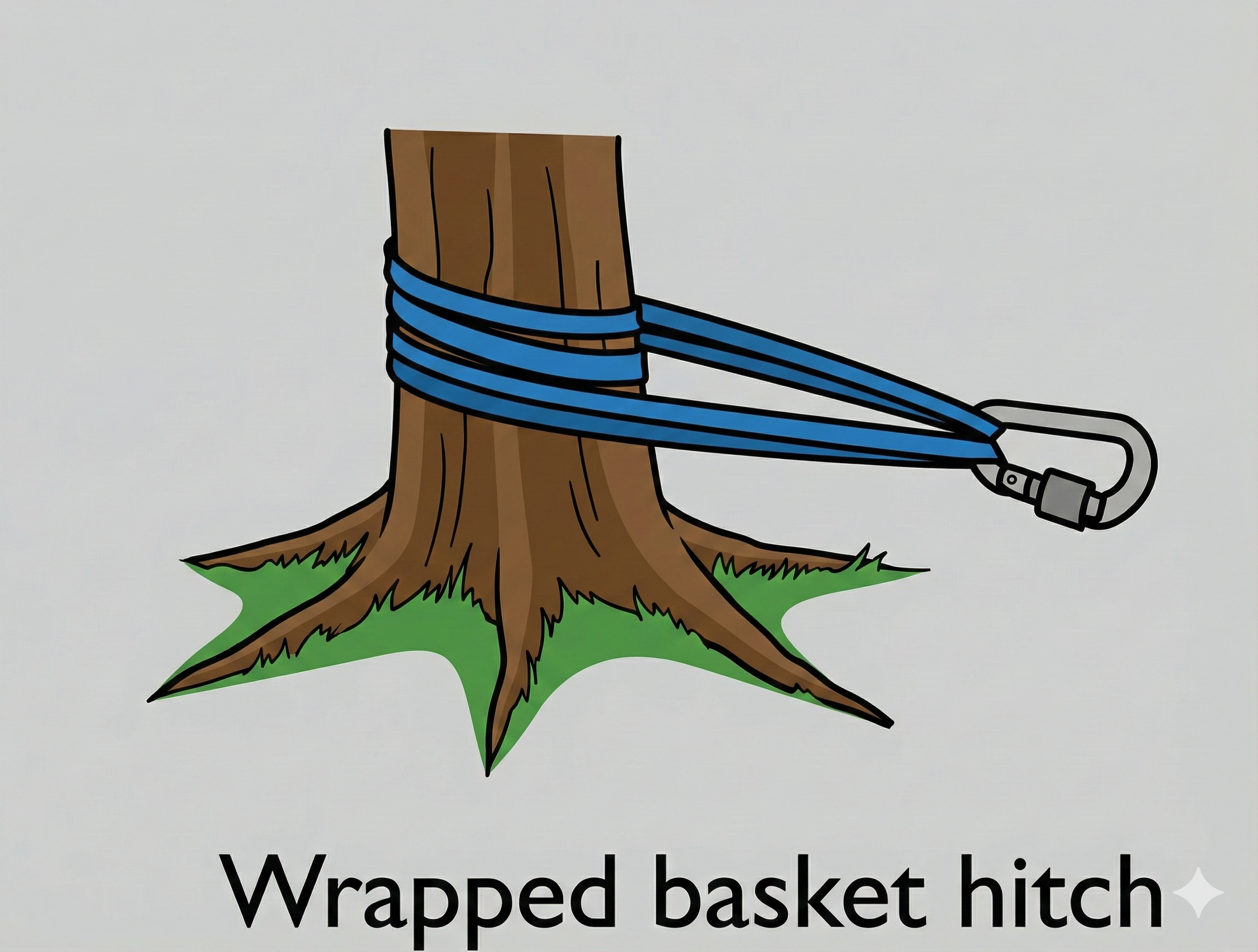

Wrapped Basket Hitch
-
What: A blue webbing sling wrapped around a tree trunk, connected with a locking carabiner.
-
How: The webbing is passed around the tree to create a full round turn (encircling the trunk completely), and the two end loops are brought together and clipped into a single carabiner.
-
Why: The wrap creates friction against the bark, preventing the anchor from sliding down the tree if the load shifts. It also keeps the stress on the webbing rather than relying solely on the carabiner.
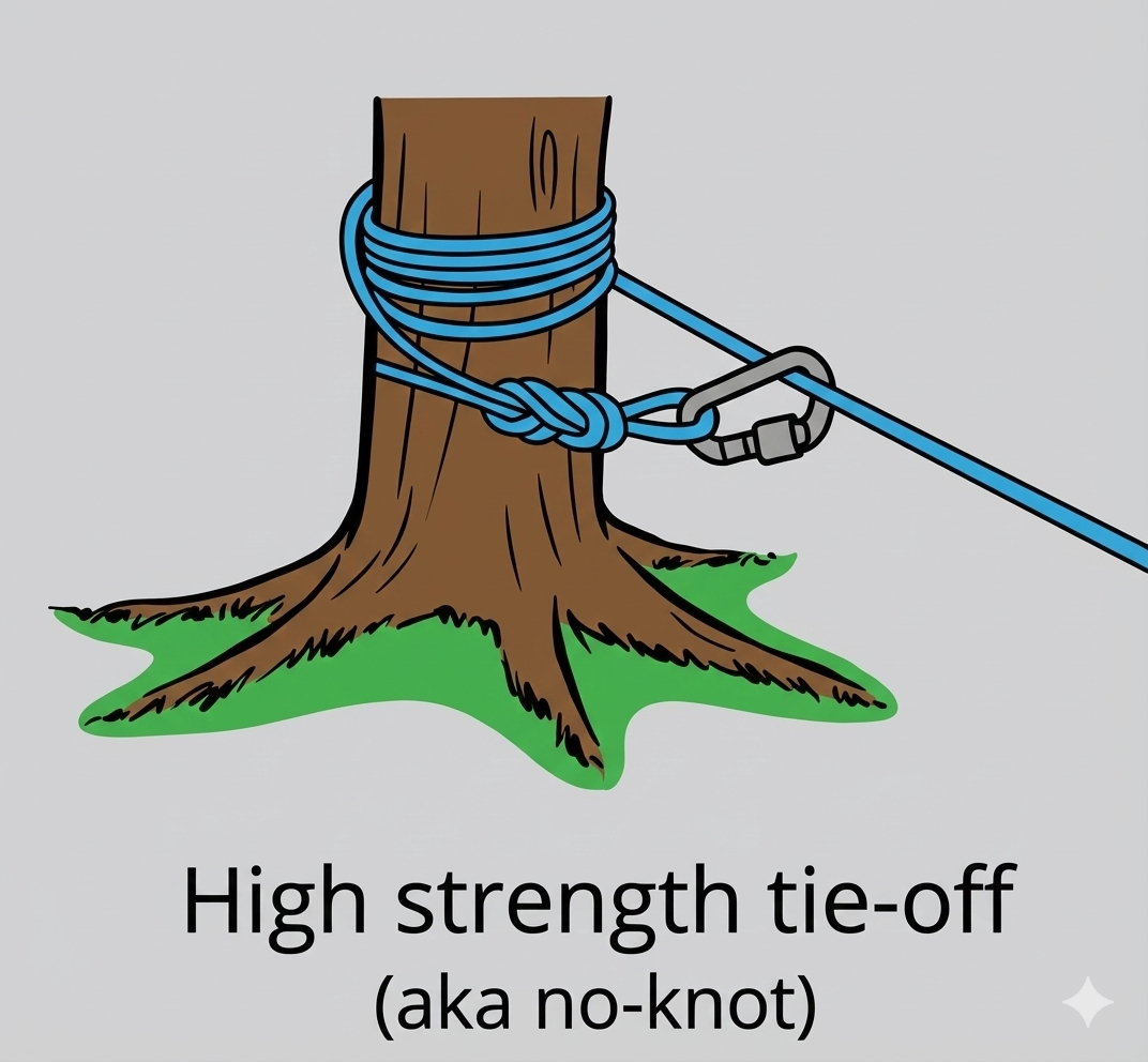
High Strength Tie-off (aka no-knot)
-
What: A blue rope coiled multiple times around a tree trunk, secured with a carabiner.
-
How: The rope is wrapped around the tree trunk several times to generate significant surface friction. A loop is tied at the very end of the rope (likely a figure 8 on a bight) and clipped loosely back onto the standing part of the rope with a carabiner to secure the tail.
-
Why: This method allows the friction of the wraps to hold the entire load rather than a knot. Since knots reduce rope strength, this “tensionless” setup maintains nearly 100% of the rope’s original breaking strength.
Rethreaded Figure of 8
-
What: A single blue rope tied directly around a tree trunk using a knot.
-
How: A loose figure-eight knot is tied in the rope, the tail is passed around the tree, and then the end is “rethreaded” or woven back through the original knot in reverse, tracing its path perfectly.
-
Why: This provides a secure, redundant attachment point without requiring a separate sling or carabiner. It is a fundamental climbing knot known for stability and safety, though it can be difficult to untie after heavy loading.
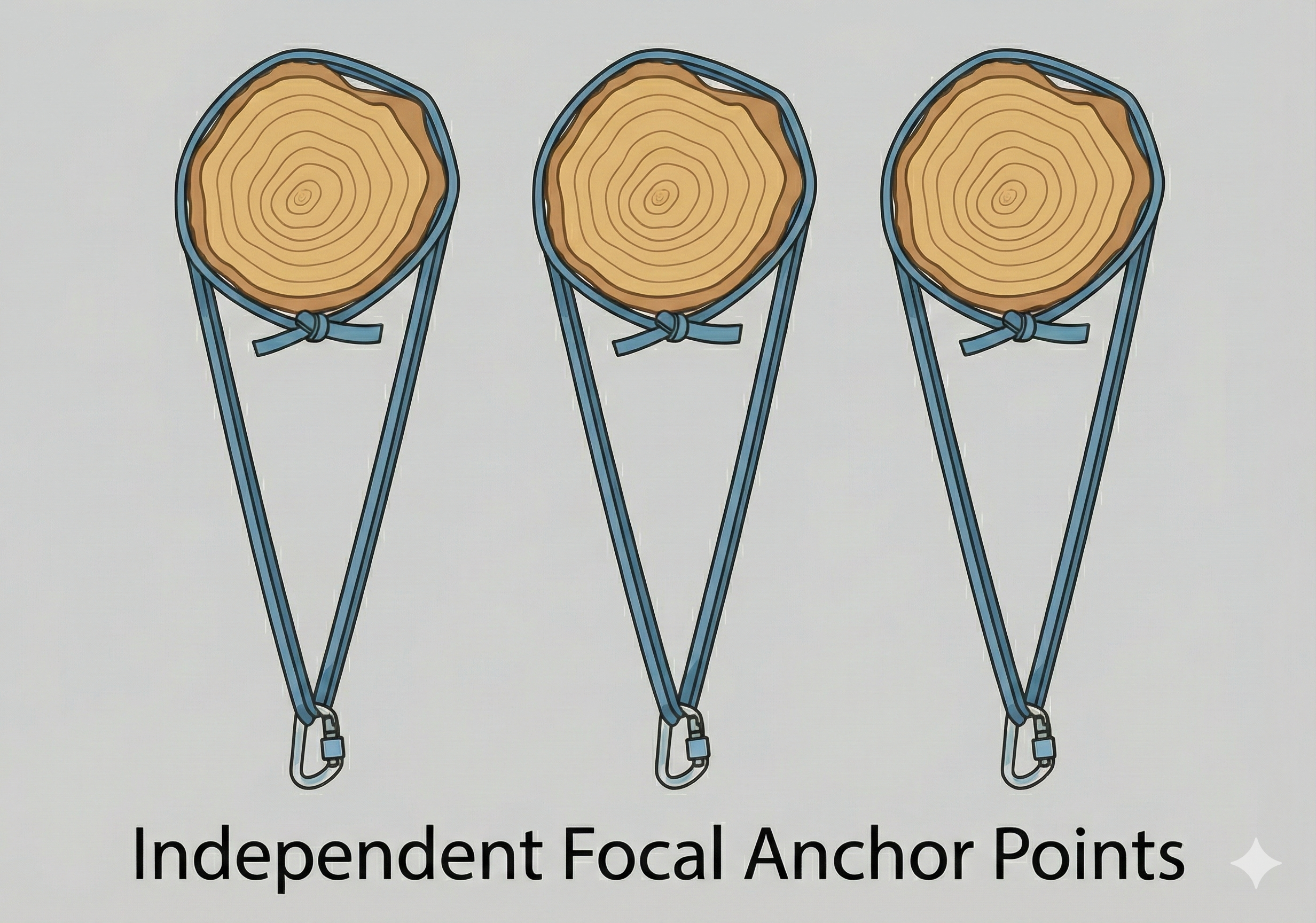
Independent Focal Anchor Points
-
What: Three distinct methods for attaching a single sling to a round anchor point, such as a tree or log.
-
How: The diagram displays a simple Basket Hitch (left), a Wrapped Basket Hitch (center), and a Girth Hitch or “Choke” (right) attached to a carabiner.
-
Why: These setups illustrate the trade-offs in rigging: the Basket Hitch is strong but can slide; the Wrapped Basket adds friction for stability; the Girth Hitch locks tightly against the bark but significantly weakens the sling material due to the sharp bend.
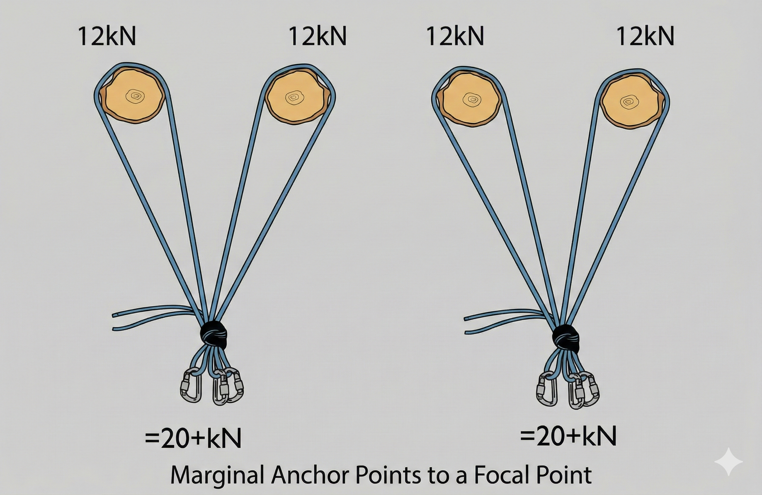
Marginal Anchor Points to a Focal Point
-
What: A load-sharing anchor system that connects two separate anchor points to a single master carabiner.
-
How: Two individual anchors (labeled 12kN each) are linked together to form a “V” shape connected to a central focal point.
-
Why: This creates redundancy and increases the total system strength (shown as 20+kN), ensuring the load is distributed and providing a backup if one anchor point fails.
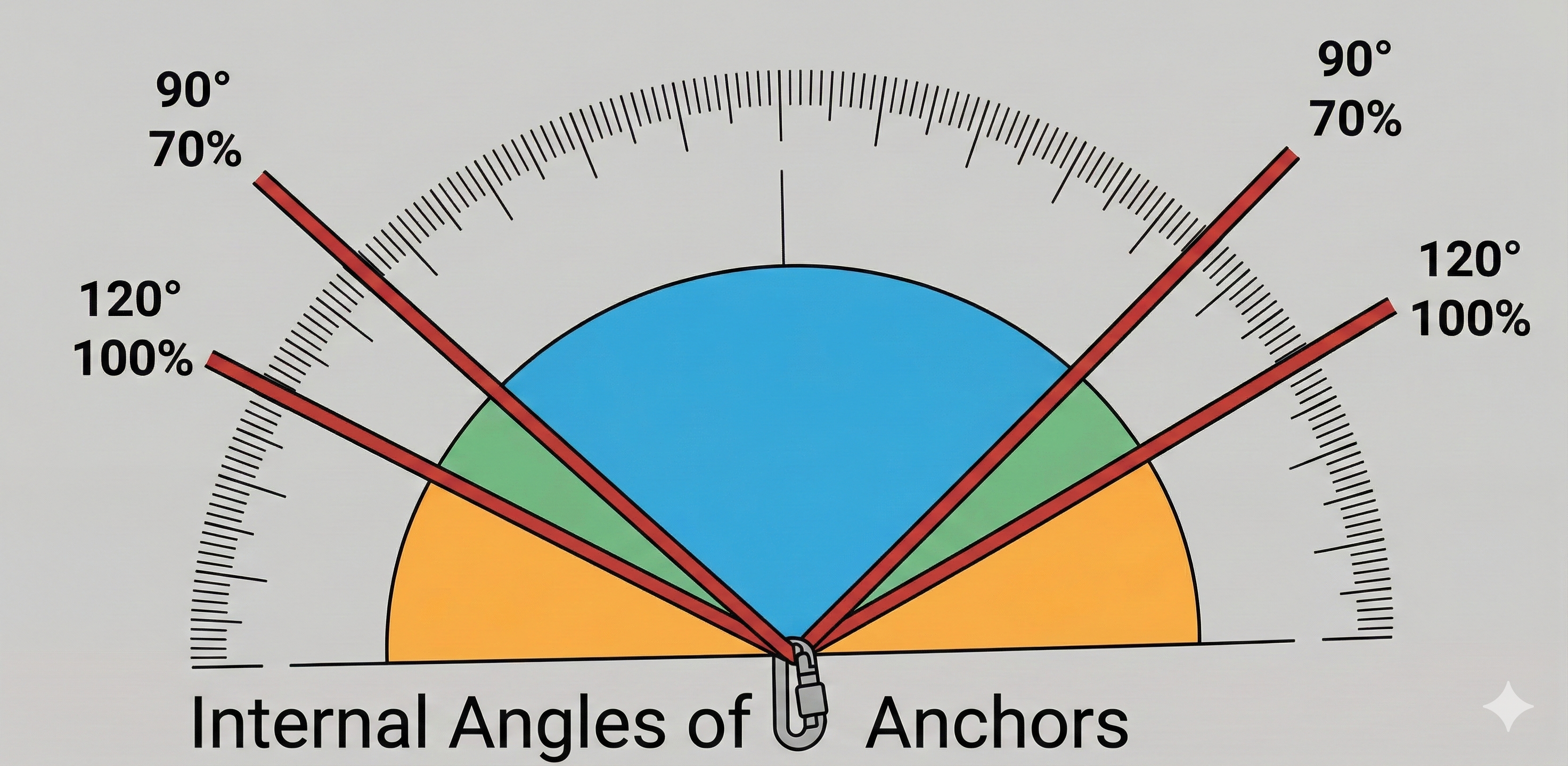
Internal Angles of Anchors
-
What: A set of diagrams and a table demonstrating how the angle between two anchor legs affects the force exerted on each anchor point.
-
How: The illustrations map specific angles (from <30° to 160°) to the percentage of the load placed on each anchor, highlighting that at 120° each anchor holds 100% of the load, and at 160° the force multiplies dangerously to 290%.
-
Why: This explains the critical physics of “Vector Forces”: riggers must keep angles narrow (ideally below 90°) to share the load efficiently, as wide angles can cause anchors to fail by multiplying the force generated by the weight.
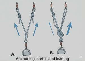
Anchor leg stretch and loading (A & B)
-
What: A comparison of load distribution between un-knotted and knotted anchor legs.
-
How: Diagram A shows two identical legs sharing the load equally. Diagram B shows a knot added to the right leg, causing the un-knotted left leg to take the majority of the load (indicated by the larger blue arrow).
-
Why: Knots tighten and deform under tension, which adds stretch to the system. The straight rope has less stretch and therefore absorbs the load first before the knotted leg can tighten enough to assist.
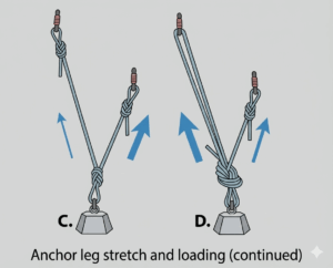
Anchor leg stretch and loading (continued) (C & D)
-
What: A demonstration of how leg length affects loading and how to correct it.
-
How: Diagram C connects a short leg and a long leg; the short leg bears nearly all the weight. Diagram D shows a knot tied into the short leg, which equalizes the force (equal arrows).
-
Why: A shorter rope reaches its stretch limit faster than a longer rope, taking the load immediately. Adding a knot to the short leg introduces slack and extra stretch, balancing it with the longer leg.
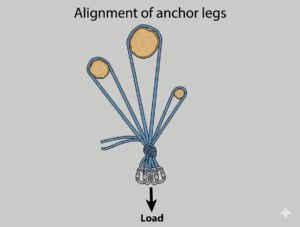
Alignment of anchor legs
-
What: A multi-point anchor system rigged to a central focal point.
-
How: Three anchor points are connected to a master point that is aligned directly with the direction of the “Load” arrow.
-
Why: Correct alignment ensures all anchor legs share the weight. Misalignment would cause one leg to take the full load while the others remain slack.
Cross-linking focal points
-
What: Two independent anchor systems connected for redundancy.
-
How: A distinct left anchor cluster and right anchor cluster are joined by a horizontal green connection between their focal points.
-
Why: This links two separate systems so that if one side completely fails, the cross-link transfers the load to the surviving system.
Back-tied anchors
-
What: A reinforcement system connecting a rear anchor to a forward anchor.
-
How: A strong rear tree is connected to the front focal tree using a tensioned line (webbing or rope). The connecting line is kept at a low angle (indicated as <30°) to align directly with the direction of pull.
-
Why: If the front anchor is considered “marginal” or insufficient to hold the load alone, the back-tie transfers the force to the stronger rear anchor, preventing the front anchor from failing or tipping forward.
Forwarding tension and floating the anchor
-
What: A complex rigging setup where the master focal point is suspended in mid-air rather than attached directly to a rock or tree.
-
How: Multiple rear anchor points are connected via tensioned lines that converge in space. The focal point (purple hardware) “floats” between them, held in position by the opposing tension of the back-ties.
-
Why: This technique allows riggers to position the focal point exactly where it is needed (e.g., directly over a cliff edge for a clean line of pull) even if no natural anchors exist at that specific spot.
Tree anchors
-
What: A “High Strength Tie-off” (or Tensionless Hitch) utilizing the friction of the rope against the bark.
-
How: The rope is wrapped around the tree trunk multiple times. A figure-eight loop is tied at the very end and clipped loosely back onto the standing part of the rope with a carabiner.
-
Why: The friction from the multiple wraps holds the entire load, meaning the knot itself is not under tension. This maintains nearly 100% of the rope’s original strength, as knots typically weaken a rope.

Boulder anchors
-
What: A natural anchor point consisting of a large, detached block of rock.
-
How: A rope or webbing sling is wrapped around the base or a stable feature of the boulder. The attachment must be positioned low to prevent leverage from tipping the rock over.
-
Why: Boulders rely on their immense weight and friction with the ground to hold the load. They are often “bombproof” (extremely secure) options when no trees or cracks are available, provided the rock is solid and immovable.
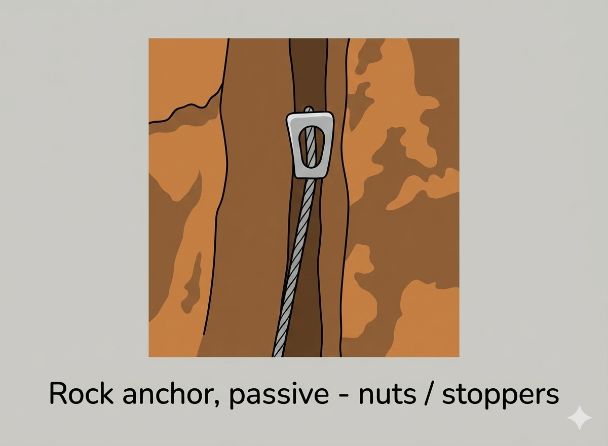
Rock anchor, passive – nuts / stoppers
-
What: A metal wedge (usually aluminum) attached to a wire cable.
-
How: The device is slotted into a constriction in a rock crack where the crack narrows. The rigger pulls it tight to “set” it, ensuring the wedge cannot be pulled through the narrower section.
-
Why: These rely on the geometry of the rock to hold the gear. They are mechanicaly simple, lighter than cams, and extremely strong when placed in a proper constriction, though they do not work in parallel-sided cracks.
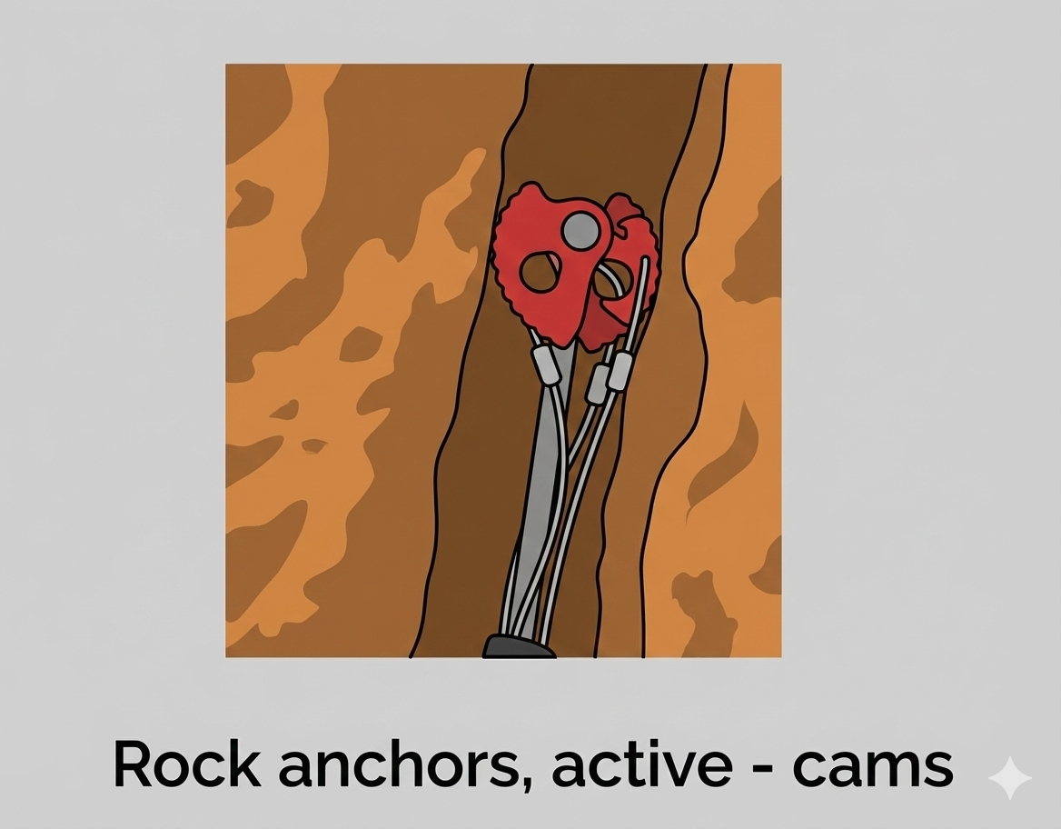
Rock anchors, active – cams
-
What: A mechanical device with spring-loaded cam lobes, often called an SLCD (Spring Loaded Camming Device).
-
How: The trigger is pulled to retract the lobes, allowing the device to be inserted into a crack. When the trigger is released, the springs push the lobes out against the rock walls.
-
Why: “Active” gear pushes outward to create friction. Under load, the cam shape translates the downward pull into outward force, gripping the rock tighter. This allows them to hold securely in parallel cracks where passive nuts would simply slide out.
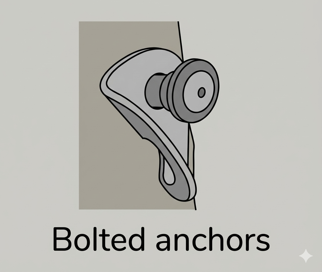

Bolted anchors
-
What: A permanent artificial anchor point installed into a rock face.
-
How: A metal hanger is secured to the rock using a bolt. The hanger features an eyelet designed to accept a carabiner or quickdraw.
-
Why: These are used in areas where natural features (like trees or cracks) are unavailable. They provide a high-strength, reliable attachment point, provided the rock quality is good.
Ground anchors skates pickets
-
What: A system using metal stakes (pickets) driven into the ground to create an anchor in soil or snow.
-
How: Pickets are hammered into the ground at a specific angle (shown as 15° leaning away from the load). They are often linked together in a series (spaced 80-90cm / 2.5-3ft apart) using rope or webbing to distribute the force.
-
Why: This setup is essential in terrain lacking solid rock or vegetation. The back-leaning angle helps drive the picket deeper into the ground under tension rather than pulling it out, while linking multiple pickets increases the total holding power.
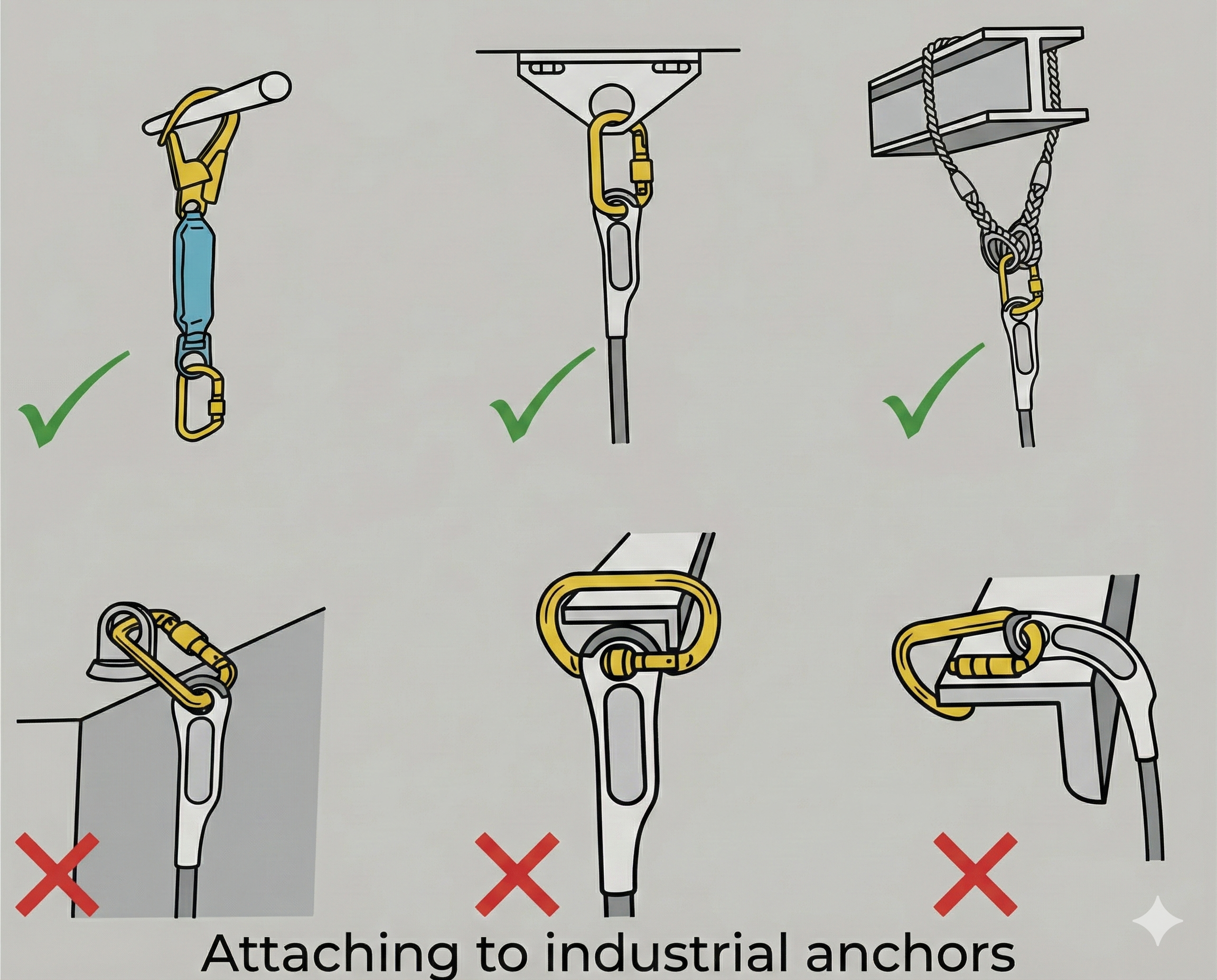
Attaching to industrial anchors
-
What: A guideline for safely connecting rescue gear to structural steel, beams, or railings.
-
How:
-
Correct (Green Checks): Using a sling or specifically designed connector that wraps around the beam or clips cleanly to a designated eyelet.
-
Incorrect (Red Xs): Clipping a carabiner directly around a wide beam or allowing the carabiner to bend over an edge.
-
-
Why: Carabiners are designed to be loaded along their major axis (spine). Loading them sideways, bending them over an edge, or forcing the gate open against a wide beam significantly reduces their strength and can lead to failure. Slings adapt to the shape of the anchor to prevent this dangerous cross-loading.

Rigging plates
-
What: A flat metal device featuring multiple connection holes (eyes) designed to organize anchor systems.
-
How: Carabiners from different anchor legs or system components are clipped into separate holes on the plate, rather than bunching onto a single carabiner.
-
Why: This declutters the focal point, ensuring components do not jam or interfere with each other. It creates a clean, readable system where forces are distributed evenly across the plate.
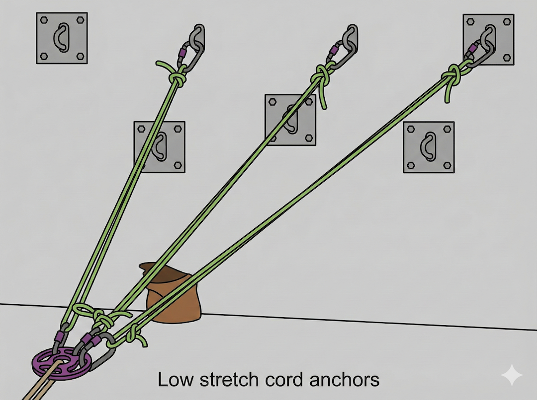
Low stretch cord anchors
-
What: A multi-point anchor system built using low-stretch cordage connected to fixed structural bolts.
-
How: Individual lengths of cord are tied from three separate wall anchors to a central rigging plate. The cords act as the “legs” of the anchor, converging to a single master point.
-
Why: Using low-stretch material minimizes the “bounce” or elongation in the system, keeping the anchor static and efficient under load. Connecting to three points provides redundancy and load distribution.
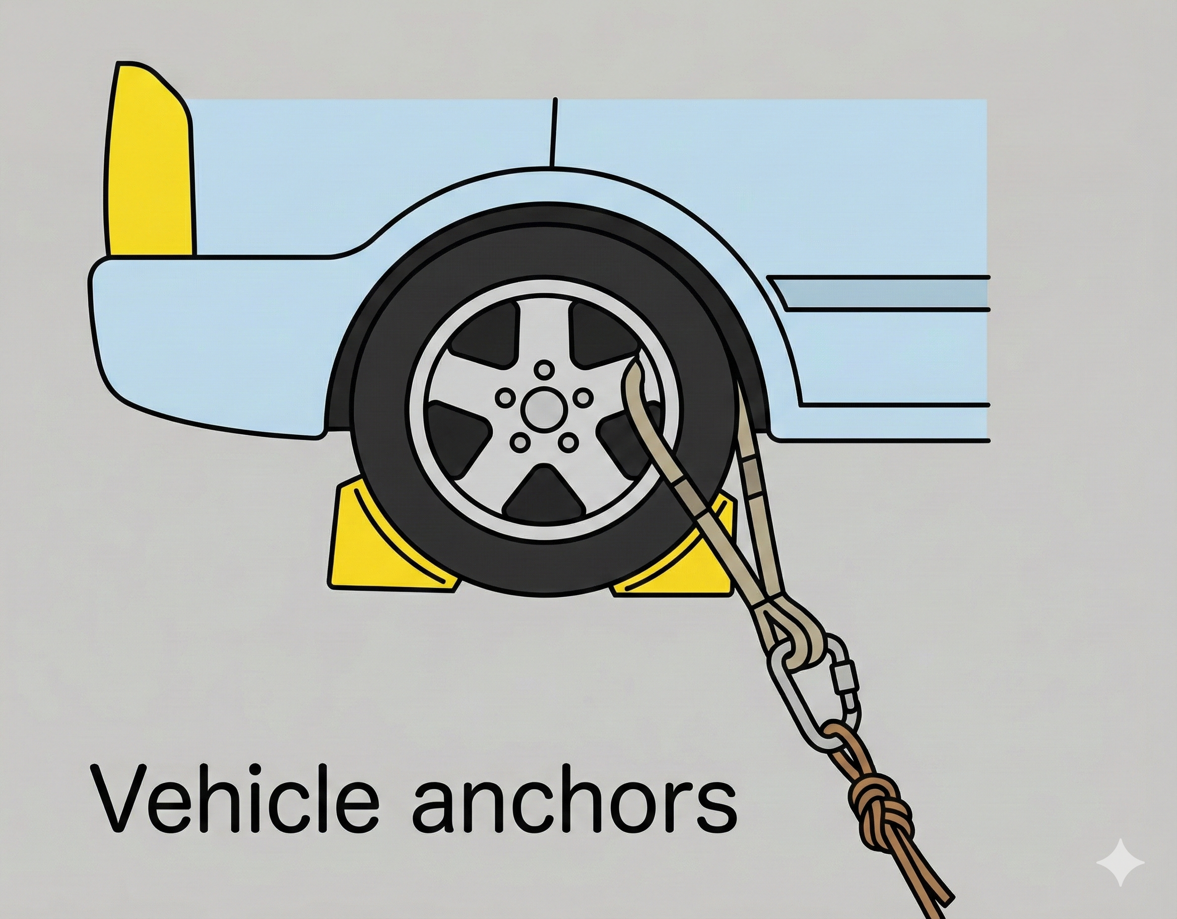
Vehicle anchors
-
What: The use of a parked vehicle as a heavy, movable anchor point.
-
How: A sling is threaded through a structural element of the wheel (the rim) to create an attachment point. Yellow wheel chocks are wedged tightly against the tires.
-
Why: Vehicles offer immense weight and can be positioned exactly where needed when natural anchors are absent. The chocks are critical to mechanically lock the wheels, preventing the vehicle from rolling or shifting under tension.
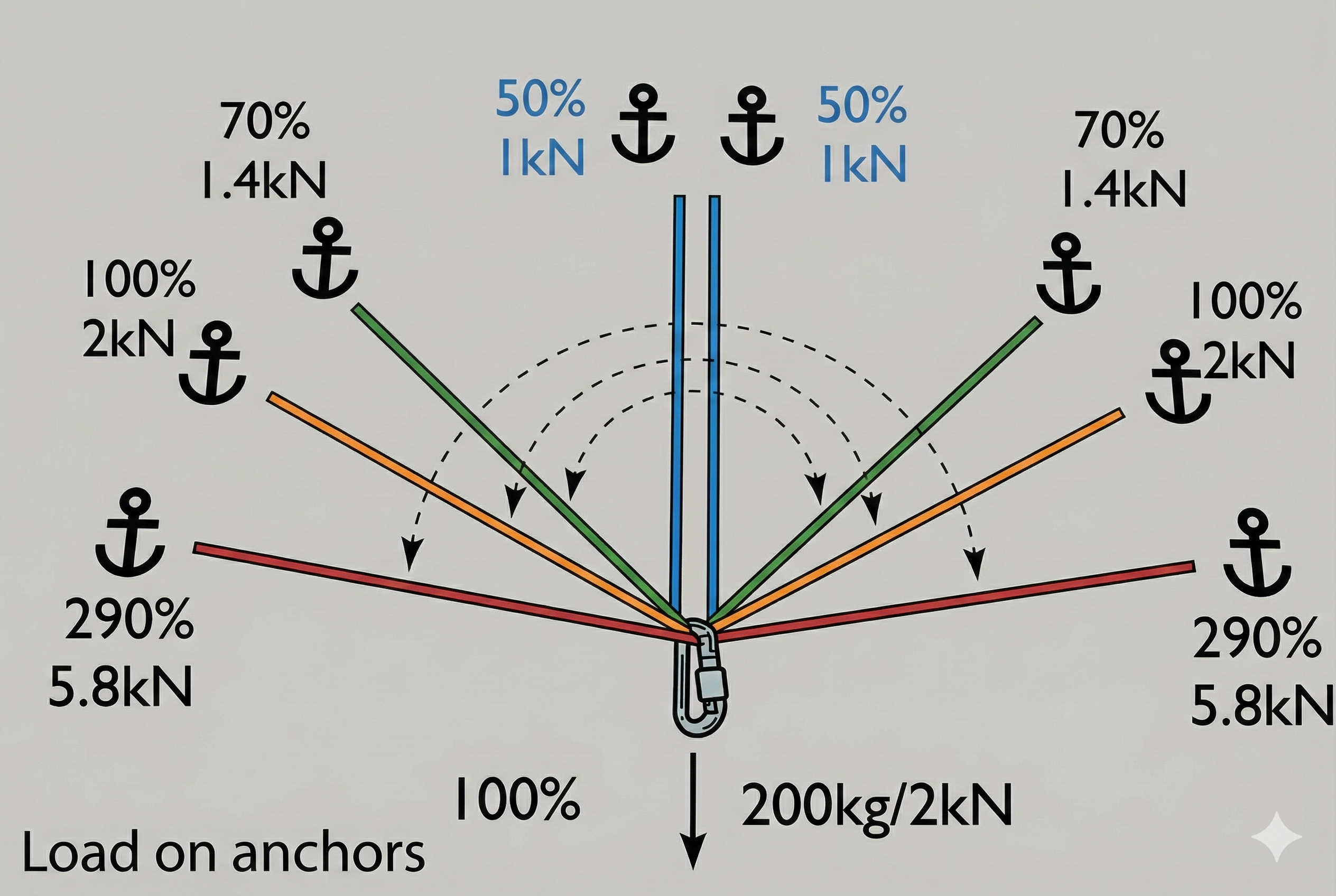
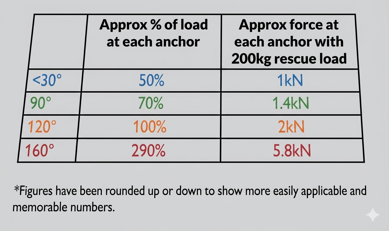
Load on anchors (Vector Forces)
-
What: A diagram and table demonstrating how the angle between two anchor legs dramatically affects the force placed on each individual anchor point.
-
How: The illustration applies a static 200kg (2kN) load to a system and maps the resulting force on the anchors as the angle widens. It highlights that at a narrow angle (<30°), the load is shared efficiently (50% per anchor), but at an extreme angle (160°), the force on each anchor spikes to 290% (5.8kN) of the original load.
-
Why: This explains the physics of vector forces: as the angle widens, horizontal tension increases. At 120° (the “Critical Angle”), the advantage of load sharing is lost (each anchor holds 100% of the load). Beyond 120°, the anchors begin pulling against each other, multiplying the force dangerously.
So in summary –
1. Fundamental Connections
The foundation of the system begins with proper material joining.
-
Tape Knot (Water Knot): The specific knot required for joining flat tubular webbing. Unlike standard rope knots which slip on flat material, the follow-through technique of the water knot maximizes surface contact for a secure bond.
2. Anchor Physics and Mechanics
Understanding the forces at play is critical to preventing system failure.
-
Vector Forces & Internal Angles: The angle between anchor legs dictates the load. Angles should be kept narrow (<90°). At 120°, load sharing ceases (100% load on each point), and at 160°, the force on each anchor dangerously multiplies to 290% of the load.
-
Stretch and Load Distribution: Loads naturally seek the path of least stretch.
-
Knots: Adding a knot to a leg introduces “give,” causing the un-knotted (stiffer) leg to take the majority of the weight.
-
Leg Length: Short legs stretch less than long legs and will bear the load first. Balancing the system requires adding a knot to the shorter leg to equalize the elongation.
-
-
Alignment: The focal point must be perfectly aligned with the direction of pull to ensure all anchors share the load effectively.
3. Natural Anchor Construction
Using the environment to build secure points.
-
Tree Hitches:
-
Basket Hitch: High strength but low friction/stability.
-
Wrapped Basket: Adds friction to prevent sliding and protects the tree.
-
Girth Hitch (Choke): Locks tight but weakens the sling material significantly.
-
High Strength Tie-off: Uses rope wraps (tensionless hitch) to maintain nearly 100% of the rope’s strength by avoiding knots under tension.
-
-
Boulders: Rely on mass and friction. Attachments must be placed low to prevent leverage from tipping the rock.
4. Artificial and Urban Anchors
Solutions when natural features are unavailable.
-
Rock Gear:
-
Passive (Nuts): Wedges that rely on rock constrictions.
-
Active (Cams): Mechanical devices that expand outward to grip parallel cracks.
-
Bolts: Permanent hangers installed in the rock face.
-
-
Ground Anchors (Pickets): Metal stakes driven into soil or snow at a 15° back-angle, often linked in series for soft ground.
-
Industrial & Vehicle:
-
Beams: Connectors must wrap the beam or use eyelets; never cross-load carabiners on edges.
-
Vehicles: Use the wheel rim (structural) and ensure wheels are chocked to prevent rolling.
-
5. Advanced System Management
Techniques for complex scenarios.
-
Redundancy:
-
Marginal Anchors: Linking two weaker points (12kN) to create one strong focal point (20+kN).
-
Cross-Linking: Connecting two completely independent anchor systems so one backs up the other.
-
-
Positioning:
-
Back-Ties: Using a rear anchor to support a forward “focal” anchor that cannot hold the load alone.
-
Floating Anchors: Suspending the master point in mid-air between rear anchors to achieve the perfect line of pull.
-
-
Organization: Using Rigging Plates to organize multiple connections cleanly and prevent gear clustering.
Peace on your Days
Lance