Using an Arizona Vortex as a Mock Aerial Ladder for Study Purposes
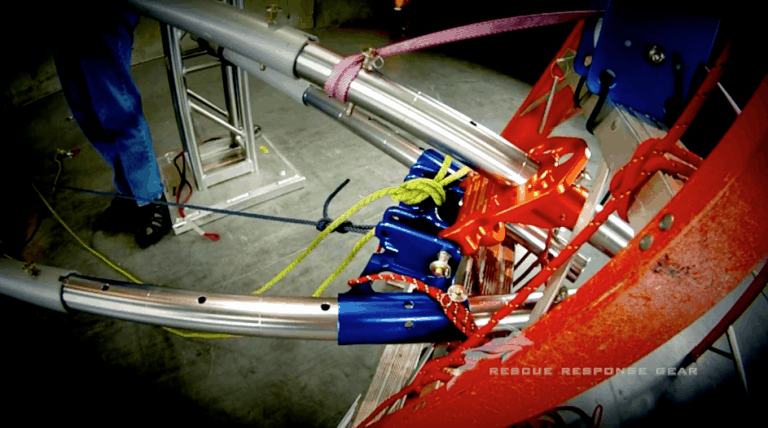
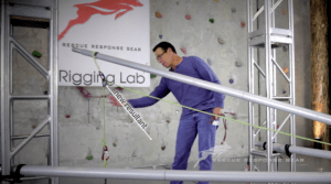
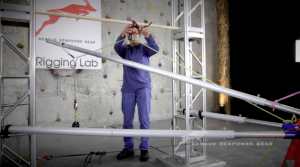
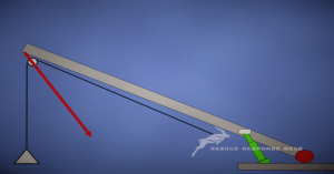
Aerial ladders are a staple in technical rescue, offering height, leverage, and adaptability in various scenarios. However, the complexity of forces acting on these structures requires a deep understanding of physics to ensure safety and effectiveness. To explore these dynamics, Rigging Lab Academy utilized an Arizona Vortex as a mock aerial ladder in its Rigging Physics II course, providing a unique platform for studying the forces and resultant effects involved in aerial ladder use.
This experiment, led by Pat Rhodes, bridges classroom theory and real-world application. It demonstrates how leveraging tools like the Arizona Vortex can replicate and analyze the physics of aerial ladders to enhance safety and operational understanding.
Understanding Aerial Ladders as Class One Levers
At their core, aerial ladders function as class one levers, with a pivot point (fulcrum) at the base and forces distributed along the ladder. The Arizona Vortex served as a scaled-down model of an aerial ladder, allowing the team to manipulate and measure forces at various angles and loads. By simulating scenarios with the Vortex, the team demonstrated how force distribution, compression, and resultant forces interact.
For example, the experiment modeled an aerial ladder extended 80 feet, with the fulcrum positioned seven feet from the pivot. The setup included a load cell to measure forces and a 4:1 mechanical advantage (MA) system to simulate real-world tension and load dynamics. This setup provided insights into tip loads, fulcrum stress, and the effects of directional pulleys versus change-of-direction systems.
Key Insights from the Experiment
1. Resultant Forces and Compression Members
One primary observation was the importance of manipulating resultant forces to maximize compression and reduce tension on the ladder’s fulcrum. By redirecting forces closer to the compression member, the stress on the fulcrum decreased, improving overall stability. This principle mirrors the design of cranes, where resultant forces are carefully managed to enhance structural integrity.
2. Directional Pulleys vs. Change-of-Direction Systems
The study compared the effects of directional pulleys and change-of-direction (CD) systems. While both configurations influenced the tip load, the directional pulley produced a slightly higher load but improved the resultant alignment with the compression member. This alignment reduced the leverage on the fulcrum, demonstrating the importance of thoughtful rigging techniques in aerial ladder operations.
3. Avoiding Common Pitfalls
The experiment highlighted the risks of rigging systems that create excessive leverage or dynamic forces. For example, rigging a mechanical advantage (MA) system straight down from the tip of an aerial ladder can significantly increase stress on the ladder. By rerouting the system through a directional pulley and building the haul system on the ground, teams can reduce dynamic effects and distribute forces more effectively.
Practical Applications for Rescue Teams
The insights gained from this study underscore best practices for rigging with aerial ladders:
- Maximize Compression: Align resultant forces with the compression member to enhance structural stability.
- Avoid Direct Loads: Rigging straight down from the ladder tip increases leverage and stress on the fulcrum.
- Use Directional Pulleys: Redirect forces to minimize tension and improve force distribution.
- Build Haul Systems on the Ground: Ground-based haul systems reduce dynamic effects and allow for smoother operations.
These principles can be directly applied to real-world scenarios, helping teams avoid common rigging errors and maximize the effectiveness of their equipment.
Expanding the Study with Rigging Lab Academy
This experiment is part of a larger body of work within the Rigging Physics II course, available through Rigging Lab Academy. The course provides in-depth analysis and practical demonstrations of complex rigging principles, empowering teams to approach challenging scenarios with confidence.
Explore more resources and courses at Rigging Lab Academy.
Conclusion
Using tools like the Arizona Vortex to model aerial ladders allows rescue teams to study and refine their rigging techniques in a controlled environment. By understanding the principles of leverage, force distribution, and compression, teams can enhance their operational safety and efficiency. As the experiment demonstrated, thoughtful rigging practices and a solid grasp of physics are essential for maximizing the capabilities of aerial ladders while minimizing risks.
Peace on your Days…
Lance




7 thoughts on “Using Vortex as Aerial Ladder”
712064 610380Aw, it was an extremely excellent post. In thought I would like to set up writing related to this additionally – taking time and actual effort to create a really great article but exactly what do I say I procrastinate alot and also no indicates manage to go done. 792684
910794 756470Hi there, just became aware of your blog through Google, and discovered that its genuinely informative. Im gonna watch out for brussels. Ill be grateful if you continue this in future. Many men and women will likely be benefited from your writing. Cheers! 594757
285090 536138Good day! Do you know if they make any plugins to protect against hackers? Im kinda paranoid about losing everything Ive worked hard on. Any suggestions? 589690
738442 305963Hosting a weblog composing facility (in a broad sense) requires unlimited space. So I suggest you to discover such internet hosting (internet space provider) that supply flexibility inside your internet space. 84896
204246 881021I definitely did not realize that. Learnt something new nowadays! Thanks for that. 543151
Regards for helping out, excellent info .
It’s a shame you don’t have a donate button! I’d certainly donate to this excellent blog! I suppose for now i’ll settle for book-marking and adding your RSS feed to my Google account. I look forward to fresh updates and will share this blog with my Facebook group. Chat soon!
Comments are closed.