A guidance system merges a descent mechanism with a tensioned rope to aid in safely lowering a stretcher, whilst ensuring it is kept at a safe distance from the surface. This technique becomes particularly useful in challenging environments, such as the rocky terrains commonly found at the base of cliffs, which make transportation to level ground arduous. Similarly, large commercial structures like hotels or office buildings, with their varying levels, widths, and heights, can pose obstacles to a secure landing. The ground underneath these buildings may be littered with smaller structures or debris from collapsed buildings that would necessitate the deployment of additional lowering systems. Industrial sites often present their own unique challenges with pipeways or other equipment that would obstruct a direct descent. However, utilizing a guidance line system enables the stretcher to be maneuvered over these hurdles.
Setting Up A Guiding Line System
A guiding line system comprises two major components: the guiding line itself and the descending apparatus. To ensure adequate coverage, the guiding line must exceed the total distance that needs to be spanned, accounting for the mechanical advantage mechanism typically situated at the base. While occasional scenarios may necessitate a top-placed tension system, the preferred and conventional position is at the bottom.
 Litter Set-Up for Guiding Line
Begin by securing the guide rope to a sturdy anchor point at the top, using a high-strength tie-off or an alternative connection method to avoid knots. The guide rope should be located significantly higher than the launch point, enabling it to elevate the stretcher above the ground and navigate any protrusions. For instance, if the stretcher is being lowered from a window, it might be necessary to anchor the guide rope on the floor above. This ensures that, once the rope is taut, it will hoist the stretcher and prevent it from descending as it exits the window.
In the subsequent step, hand over the guideline to the team responsible for setting up the lower end. Depending on the space in between, you might be able to throw the rope or you may require a line gun to dispatch a messenger line over the area you intend to traverse. Alternatively, a rescuer could rappel down and navigate through the boulders or urban barriers blocking the path; the system can generally be established at the guiding line’s top as there’s often more room at the lower end. This approach might also be faster if the team is already stationed at the bottom.
To establish an anchor, you’ll need to connect a guideline to it using a mechanical advantage (MA) system. Placing the bottom anchor further out from the base of the slope increases the lift of the guideline. A 5:1 MA system may be necessary if you lack manpower. However, for steeper slopes, a 3:1 MA system may suffice given the reduced force required for tensioning. For tensioning estimates, use similar standards to high lines: for knot-free ropes, apply a factor of 18 for NFPA G-rated ropes and a factor of 12 for NFPA T-rated ropes. This factor is calculated by multiplying the mechanical advantage by the number of individuals tensioning the system.
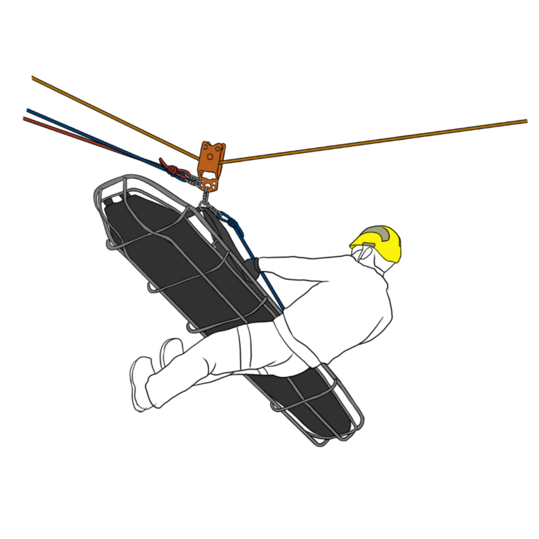
Begin by setting up a primary line and a safety (belay) line at the top. Ensure you leave ample space between the anchors and the edge to accommodate the stretcher and the personnel handling it. Over the guiding line, position a high-line carriage or large pulley, to which you will connect the stretcher harness. The primary line is then joined to the carriage or pulley, maintaining alignment with the track line, particularly when navigating the stretcher around impediments. Lastly, the safety (belay) line is hooked onto the carriage or onto the O-ring on the stretcher harness.

 Load Primarily on the Lowering Line Load Primarily on the Lowering Line |
 Load Primarily on the Guiding Line Load Primarily on the Guiding Line |
In essence, the guiding line system initially functions as a lowering mechanism with the guiding line pulley serving as a mobile high anchor point. If the guiding line is suitably positioned above the edge, applying tension to it will cause the litter to rise and move over the edge. When dealing with a tended litter, only apply enough tension on the guiding line to ensure that the carriage does not interfere with the litter and tender. During the lowering phase, the system mirrors a traditional lowering system incorporating a main line and a belay. System failure of the guiding line at this point would not result in any adverse effect on the system.
The purpose of the tenser is to maintain a safe distance between the litter and the wall. In scenarios where the litter is unattended, ensure the tension on the guiding line is just sufficient to prevent the litter from bumping against the wall or running into obstructions.
As the litter approaches a position requiring it to be pulled away from the face or hung over the surface, adjust the tension on the guiding line to elevate the litter, ensuring it’s just enough to bypass any obstacles.
When the litter reaches a path where the tender can move on foot, the tender can disengage from the tender system, significantly lightening the litter and consequently reducing the necessary tension on the guiding line to maneuver the litter. The tender can then follow alongside the litter, assisting in navigating it around obstacles. The tension in the guiding line can be ramped up to hoist the litter over obstacles and then loosened to keep the litter close to the ground.
By maintaining the litter at about one or two feet above the surface, the requirement for a secondary line as a failsafe is negated. The risk of a fall is minimized, and the possibility of injury is considerably reduced while the litter remains close to the ground.
 Skate Block with a back-up device belay Skate Block with a back-up device belay |
 Skate Block System Skate Block System |
A Skate Block system is a specific type of Guiding Line, primarily utilized in evacuations from vertical structures, like towers. Unlike the Guiding Line, which is meant for low-angle or more horizontal operations, the Skate Block system’s main purpose is to separate the load from the structure or surface to prevent interference. This eliminates the need for a tender to navigate the load, leading to quicker operations that require fewer personnel.
In many rescue scenarios, the Skate Block system is employed for lowering, but it can also be useful for raising, for instance, when shifting a litter towards the subject. The distinctive aspect of the Skate Block system compared to a conventional Guiding Line system is that it doesn’t necessitate an extra rope for the guideline. Rather, the control lines also serve to guide the load away from the structure.
Rigging the Skate Block System
The Skate Block system is remarkably efficient in terms of manpower. Equipped with the right tools, a single individual can manage a dual-tension Skate Block lowering operation from the ground, making it an excellent choice for small teams working on communication or power transmission towers.
The assembly of the Skate Block can be achieved with three typical rope rescue systems – a conventional loaded main/belay, a single loaded main line featuring an automatic traveling belay, or a dual tension system. The benefits of these dual tension systems have been extensively discussed in previous courses.
The design of the system includes a rope that extends from the subject or litter to a directional change pulley situated above the subject. This rope then descends towards the descent control device stationed at the ground anchor.
The “skate block” is essentially an additional pulley mounted on the descending rope, which is then connected to the subject or litter. As the lowering process commences, this pulley steers the subject along the rope segment that descends towards the lowering device and anchor. This aims to pull the subject away from the structure and guide them towards the anchors.
The positioning of the lower anchor is crucial, as it should not be located directly under the load. If it’s too close, it won’t help keep the load clear from the structure, preventing potential entanglement. Conversely, it shouldn’t be too distant, as the more horizontal the lines become, the harder it is to operate, and ultimately, it will cease to function. A general guiding principle is to maintain an angle of 15-30 degrees, depending on the lowering distance.
Traveling Belay
In a travel belay system, the rope is anchored on a structure above the starting point, then threaded through an automatic belay device like an ASP. This device is connected to the individual being lowered. Alternatively, a slack belay system could involve a second rope attached to the individual, run through a belay device secured and operated from above, or redirected through a pulley to a manual belay device below.
If dual Clutches are employed as lowering mechanisms, a single rescuer can efficiently manage both lines. This necessitates that both anchors be near enough for the operator to reach both Clutch handles simultaneously. The most straightforward method to achieve this is to attach both Clutches to the same anchor plate.
Skate Block Operation
For optimal safety, it’s crucial to connect both ropes at the same point on the subject’s harness or litter. Avoid fastening one rope to the waist attachment and the other to the dorsal – this could lead to an uncomfortable and hazardous rocking motion unless the ropes are perfectly synchronized. The change of direction pulleys above the subject should also be near to maintain stability.
If the system’s objective is to hoist the subject, a change of direction should be implemented, and a hauling system should be assembled at ground level. However, if the subject needs to be elevated and the hauling system must be constructed at an upper level, a skate block will be ineffective. In this case, either a Guiding Line or a traditional system with an attendant or control line would be required to maneuver the patient appropriately.
Peace on your Days
Lance