
We have a lot of members and non-members alike asking about aerial ladder work and whether or not we have ever done any sort of course or mini-rigging study on them. This is obviously a huge undertaking and one we’d love to do and plan on doing it. However, in the meantime, I want to bring out one such example of work we had done a few years ago with Pat Rhodes at the helm. This video is part of a large body of work within our course Rigging Physic 2 with Pat Rhodes. Enjoy! And if you need more information this type of thing, head over to Rigging Lab Academy.
Aerial Ladders use as an Artificial High Directional | Rigging Physics 2 |
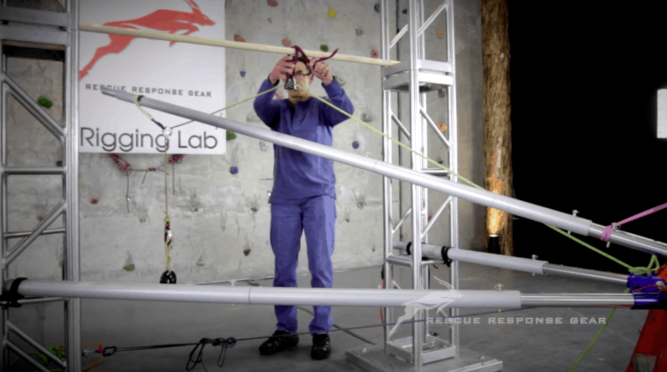
 Well, we’re back in the Rigging Lab and this class that we’re conducting right now is Rigging Physics II. One of the things that we’ve been exploring mathematically inside the classroom was the effects of using an aerial ladder. What we have here is a model of an aerial ladder and we use the Arizona Vortex to accomplish this goal.
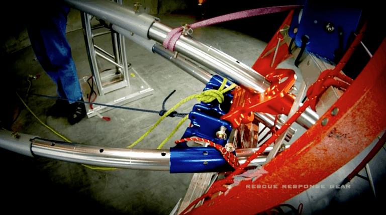
With an aerial ladder, we have a class one lever basically. We have the aerial extension and of course on an aerial ladder, there would be a ram here that is controlling the up and down movement, the elevation of the stick. Well, we don’t have a ram, but the way we have compensated for that is we have an under tension here with a set of fours coming to where the fulcrum is, and that’s connected to the load cell, and that’s how we’re getting our readings.
The ratio right now is 11 to one. This represents an aerial ladder that would be extended 80 feet over a fulcrum that’s roughly seven feet back from the pivot point. So, our ratio is a 11 to one. In this case, we’re also looking at the effects of the resultant in a couple of different scenarios. So, we have a four to one with a change of direction coming straight off the tip of this aerial ladder, this hypothetical aerial ladder. Our weight is two and a half pounds.
 The classroom on the simulation we did mathematically is a 300 pound load, and we can see that we had a tip weight of 375 pounds. In this case, it’s roughly three pounds with a four to one CD and in just the static state, no hauling or anything. All we’re looking is static weight. We have a resultant almost worse case scenario if this was a class one lever and I’m pushing down on this end, I’d be pushing down perpendicular to this lever. This is a 20 degrees elevation, so the load cell right now is reading 36 pounds. That’s kind of consistent with what we did mathematically in the classroom.
In this configuration, we had that 375 pounds was up around 4,000, a little bit more mathematically and that could be the difference in a couple of things, maybe the elevation of our model right here and some other factors, but what we’re looking at is we’re seeing that this is in the ballpark. We’re getting some real life comparisons of the math that we did in the classroom.
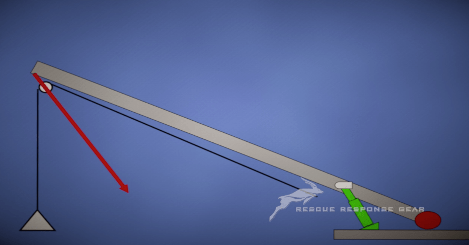
Once again, this is a four to one with a CD. The resultant force is coming straight down in this fashion right here. The tip load on the four to one CD is going to be less than when we put it through a directional pulley. I’m not concerned about the tip load. What we’re concerned about is what kind of leverage we’re putting at the fulcrum.
 What we’ve changed over to here is a directional pulley instead of the four to one with the change of direction. We have a new resultant. Our resultant is finding the halfway point between this component and this component. It’s this force that’s coming right back here. Now, the resultant has become a little bit closer to the compression member. Another observation is that because of this angle, which is about a 70 degree angle right now, we know it’s 70 degrees. We’re going to have about 164% of the load at the tip. At two and a half pounds, we have roughly a four pound load. We have almost an additional pound of weight at the tip.
With the four to one CD, it was three pounds. With the directional pulley, it’s four pounds now, but because of this improved resultant and because we’re getting our forces closer to the compression member, we should have an improved rating on our fulcrum. Whenever possible, maximize the compression of the anchor and try to minimize the tension.
By maximizing the compression of this lever, we should even further reduce the leverage that we have on the fulcrum. If I were to raise up from here, we’ve taken it down to seven pounds on the hit. We could take this all the way to zero to where it’s coming straight down the compression member.
 Probably the best example, take a look next time you’re around a construction site and you’re seeing some cranes. Crane manufacturers are great for maximizing the compression of the crane by manipulating the resultant. That’s what they’re doing. They’re manipulating resultant forces. This might be a mast head coming up right here some other form of high directional on the crane itself taking the resultant at the end, driving it back down the crane.
Other ways to maybe manipulate this resultant that you’re using an aerial ladder is maybe have another influence on the downside. Possibly, I have a directional pulley that’s adjustable, a deflection offset, or a dynamic directional that allows me to flex my resultant back up in this direction.
This kind of factor will allow us to maybe even move this load on a aerial ladder forward and backward, maybe getting over obstacles, that sort of thing. We all know that there’s been a fairly robust history in the United States of aerial ladder failures with people that are teams, fire departments that have rigged off the tip of an aerial ladder. The thing that you probably want to avoid is coming straight down this aerial ladder which is a common practice in a lot of places where they’ll use a mechanical advantage straight down, and we’re not even getting into the dynamic effects of this system. Right now, we’re just looking at statics.
 With dynamic effects of a single person pulling down on a three to one with a change of direction would add even more stress to it. With this kind of scenario with a haul team on the ground doing the hauling a lot smoother, we’d have a lot less dynamic effects. The preferred way to rig an aerial ladder would be to come up through a directional pulley, run it back down the belly of the aerial ladder to the ground, build your haul team, your haul system on the ground. Of course, there’s other factors that we can do to maximize our compression by putting the resultant force back down in line with the compression member.
[thrive_leads id=’51590′]
Peace on your Days…
Lance


7 thoughts on “Using An Arizona Vortex as a Mock Aerial Ladder For Study Purposes”
712064 610380Aw, it was an extremely excellent post. In thought I would like to set up writing related to this additionally – taking time and actual effort to create a really great article but exactly what do I say I procrastinate alot and also no indicates manage to go done. 792684
910794 756470Hi there, just became aware of your blog through Google, and discovered that its genuinely informative. Im gonna watch out for brussels. Ill be grateful if you continue this in future. Many men and women will likely be benefited from your writing. Cheers! 594757
285090 536138Good day! Do you know if they make any plugins to protect against hackers? Im kinda paranoid about losing everything Ive worked hard on. Any suggestions? 589690
738442 305963Hosting a weblog composing facility (in a broad sense) requires unlimited space. So I suggest you to discover such internet hosting (internet space provider) that supply flexibility inside your internet space. 84896
204246 881021I definitely did not realize that. Learnt something new nowadays! Thanks for that. 543151
Regards for helping out, excellent info .
It’s a shame you don’t have a donate button! I’d certainly donate to this excellent blog! I suppose for now i’ll settle for book-marking and adding your RSS feed to my Google account. I look forward to fresh updates and will share this blog with my Facebook group. Chat soon!
Comments are closed.